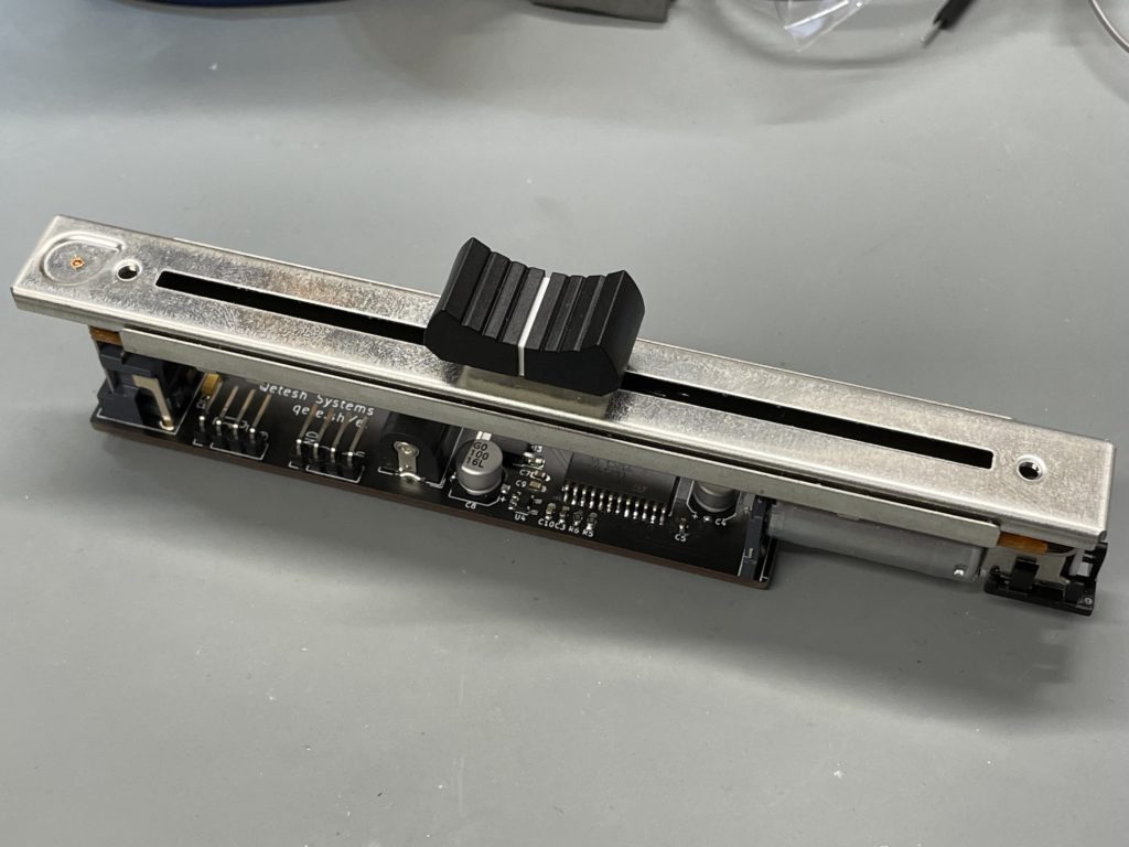
For an upcoming project, a custom controller for one of my all time favorite games Kerbal Space Program, I need a throttle control but since the game has other ways to set the thrust, I want the hardware to follow changes in the software. The idea to use a motorfader, like it’s used in studio tech, came up. So I got one of those, in this case an ALPS RSA0N11M9A0.
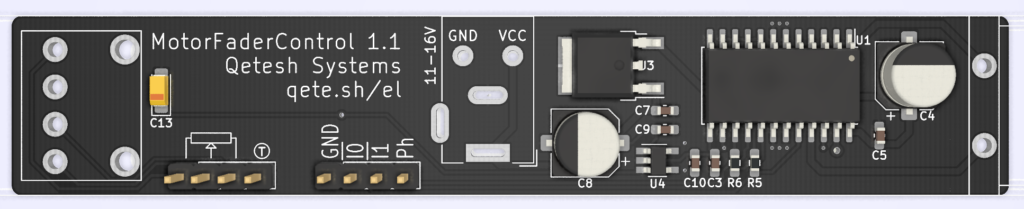
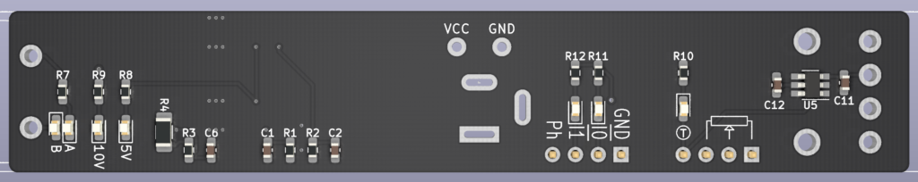
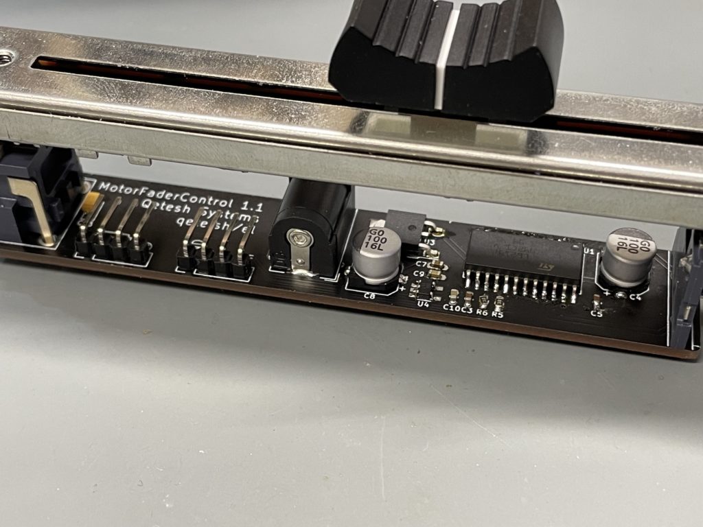
After poking around and looking for ways to properly control the extremely fast motor which can propel the slider from one end to the other in half a second, I ended up getting a L6219 Stepper Motor Driver which is able to handle the specs of this motor (10 volts with 800mA peak current). After testing my circuit, which is mostly based on the L6219 specs, I designed the board to fit under the fader, making sure it does not get wider than the faders foot print so it will be possible to mount more of them next to each other if needed. All needed pins are lead out to simple header pins and everything needed is on the board so it is possible to hook up just a microcontroller without any extra parts.
The board has a two built in voltage regulators, a BAJ0BC0FP-E2 (10V, 1A) to power the motor and a AP7370-50WW (5V, 300mA) to provide stable 5 volts for logic. I also added TTP223-BA6 which is a simple touch pad detector IC to read the built in capacitive touch sensor of the fader and feed that back as a logic signal.
A few LEDs to show the status of different parts while the board is running were added as well, which is very helpful for debugging while writing the software!
In case you want to use my idea, here’s the gerber files to get the board produced. I use JLCPCB (not a sponsor) to get my boards done and I am quite happy with them. If you use them as well, make sure to check “Specify a location” for the order number since it’s put under the IC then so it wont be visible on the finished board.
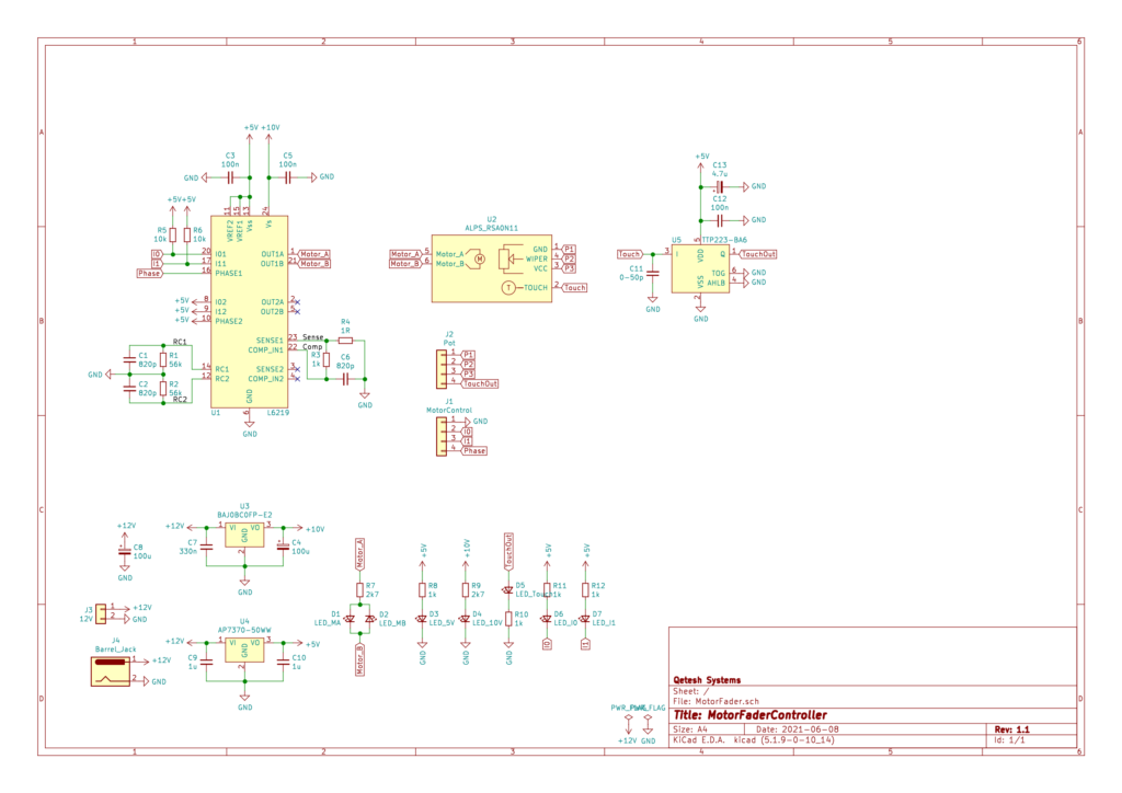
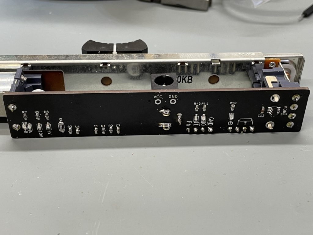
To control the motor, the Ph(ase) pin needs to be pulled up or down to set the direction and pulling the I0 and I1 pins low will actually run the motor. I just tied them together which works fine for me but pulling just one low allows to run the motor with 1/3 or 2/3 power (See L6219 datasheet for details).
After some trial and error I found a 50% duty cycle pwm signal on the I0 and I1 pin to work very well and give a smooth movement of the motor. Just make sure that you permanently read the curent position of the pot to keep the slider from slamming into the end position. It will survive a few of those impacts (speaking from experience) but it is probably not a good idea to do that too often!