My server rack needs cooling. Not much but a little airflow won’t hurt. The problem: fans on full speed are loud, even the silent ones, and just lowering the voltage was boring. I looked for fan controller hardware but they were either too expensive, too big or just didnt offer what I needed which was the reason for this little project…
My requirements:
– Able to control at least 3 12V fans in parallel
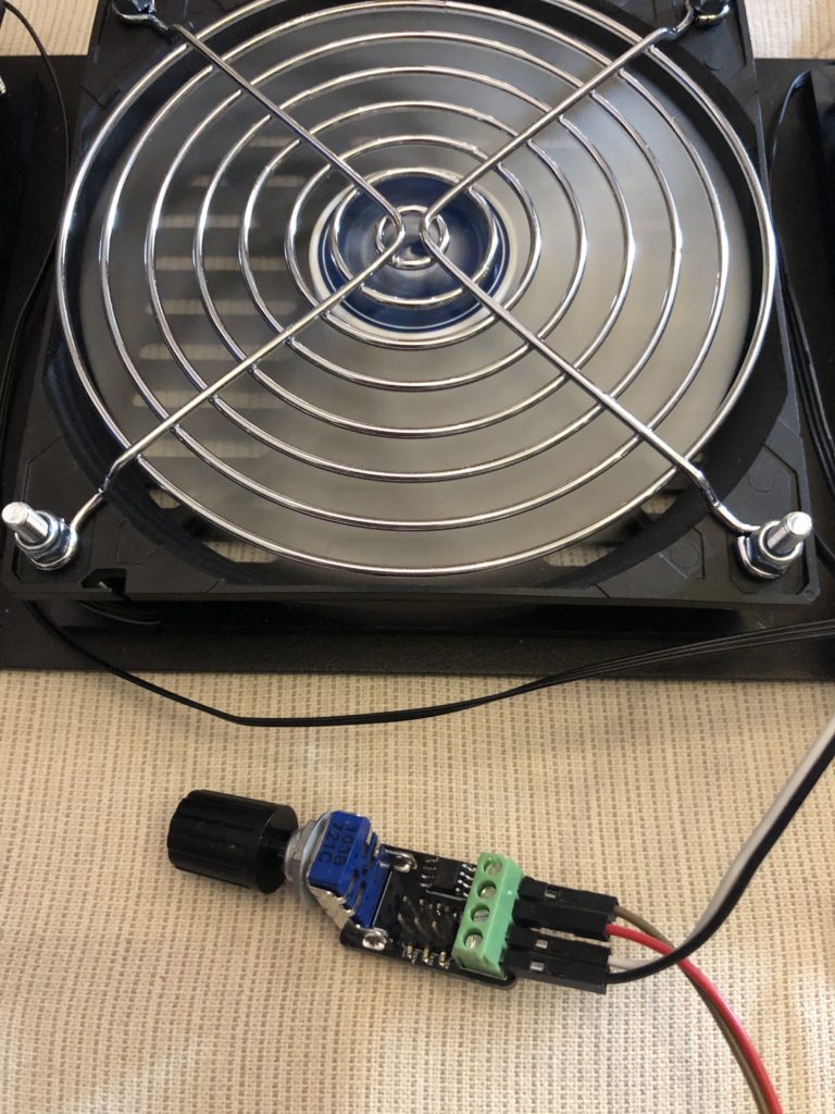
– Small and light enough to be held just by the potentiometer
– Cheap (< 5€)
– Easy(ish) to assemble
– Min and max values must be adjustable
– Should use as many parts from my existing inventory as possible so I don’t have to buy lots of new stuff for it
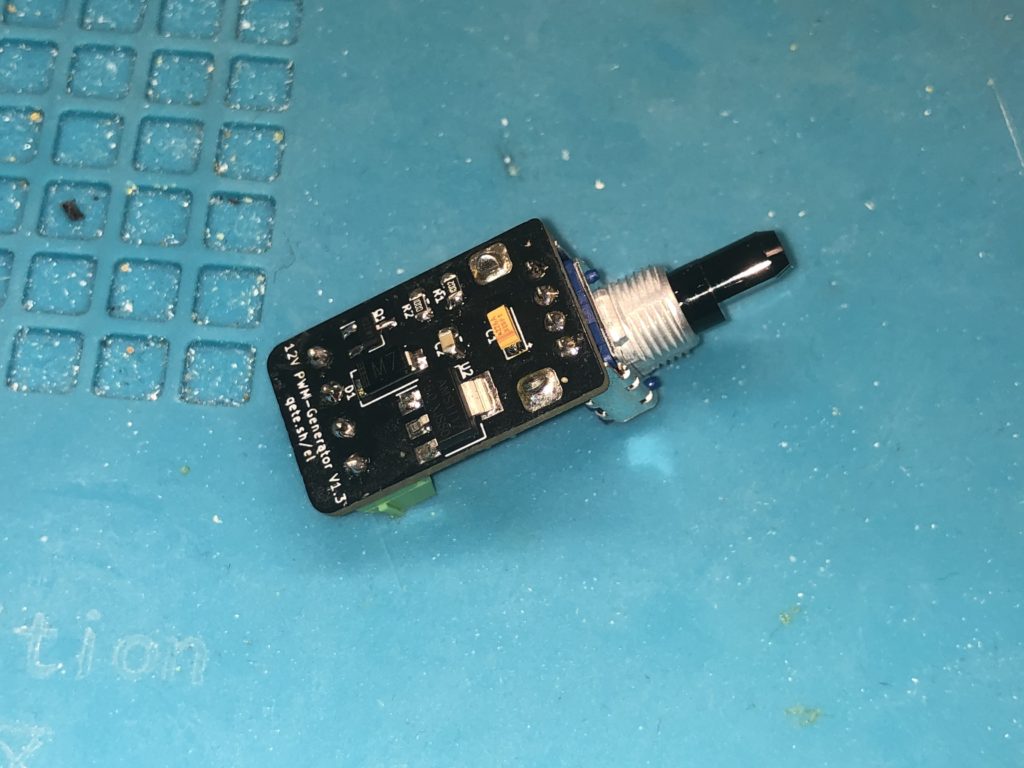
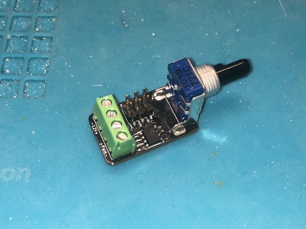
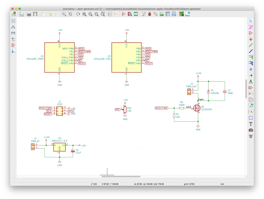
Since I already got a bunch of Si2302 N-Channel Mosfets I decided to use those to switch the output – they can handle a constant load >2A which is enough for several fans. For the input I am using a relatively high quality 10kΩ potentiometer from ALPS with a mounting bracket so it can hold the whole assembly in place without extra screws. To keep it as cheap as possible and since the program running will be rather small anyway I am using the ATtiny13A microcontroller which I can get for ~60 cents. It is definitely one of the smallest microcontrollers that has Arduino support. A standard AMS1117-5.0 voltage regulator provides stable 5V for the ATtiny.
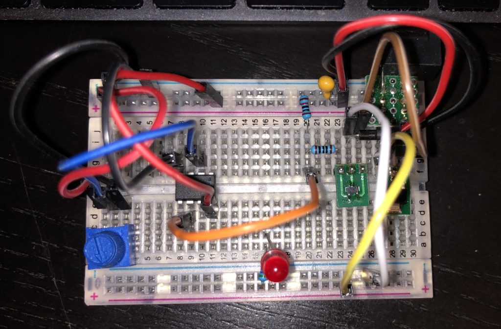
A first prototype was built on a breadboard to see if my design works and to do some simple tests. It is using all the planned parts, just some of them as THT instead of SMT of course. That prototype also helped me realize that the capacitor is probably a good idea so it was added to the final version as well.
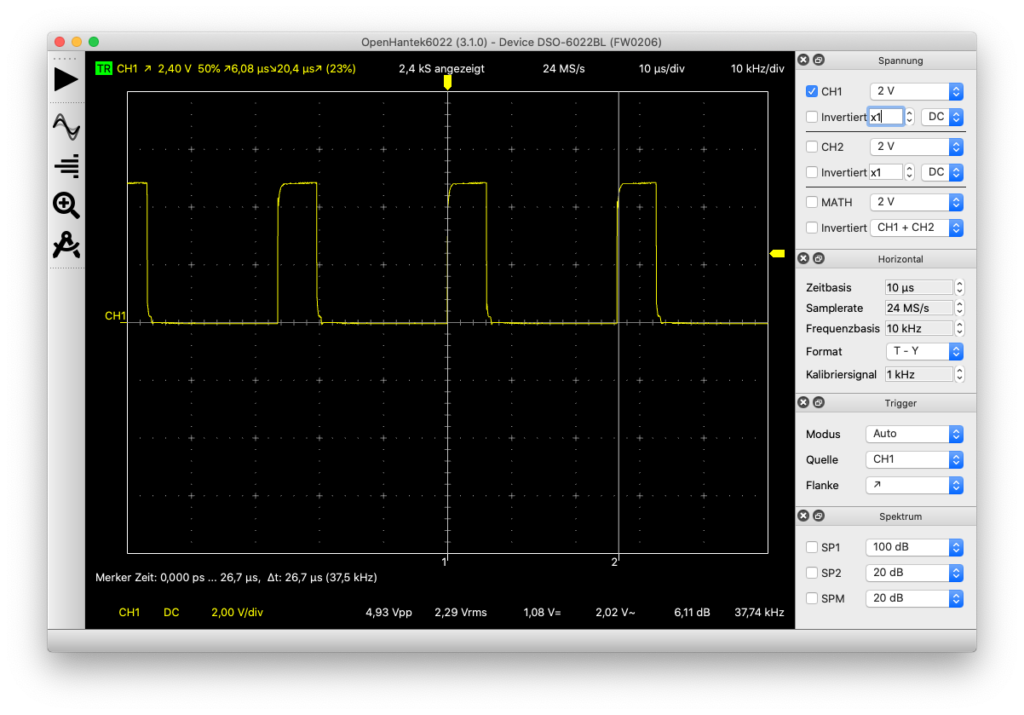
If you decide to build this project you can replace the ATtiny13A with an ATtiny25, 45 or 85 – all of them are pin compatible and the sketch runs on them with little to no modifications. I am running the µC on 9.6MHz using its internal oscillator. That way the generated PWM can pulse with ~37.5kHz (CPU-Frequency / 256) which is high enough to run the fans without audible noise. PWM frequencies below 20kHz are quite audible and often extremely annoying. The ATtiny25/45/85 can run on 8MHz which then generates a 31kHz signal – still more than enough.
Since the fans can cause a lot of noise when run pulsed, I added the option to have a small capacitor in parallel to them – it is not needed but smoothes the output a lot. I guess with a faster flyback diode I wouldn’t have that problem at all. But since I went cheap on it I use the 1N4007 diodes I had in stock – I know they aren’t perfect for this scenario but it works. The power spikes before the diode kicks in go up to 16 volts which is fine for the chosen mosfet. With a 100nF capacitor in place the spikes are gone completely. You might have to use a different diode or another capacity if you’re running different fans. In case you’re using this to drive LEDs you can skip both of them – the capacitor can even be counter productive in that case.
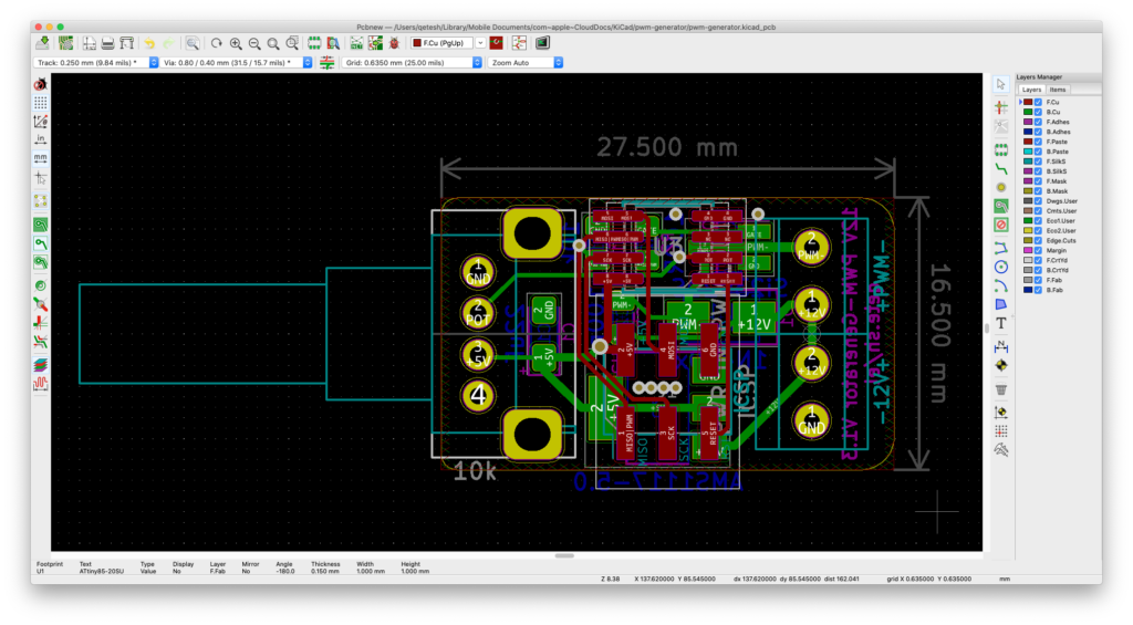
My board supports both the 200 mil (-SU) and the 150 mil (-SSU) versions of the ATtiny – the 150 mil versions are usually cheaper but sometimes not as easy to get. If you program the µC before soldering you can skip the ICSP header but I prefer being able to change the program later. It also acts as a heatsink for the AMS1117 (Not that it’s really needed with this kind of load)
The board was designed in KiCad and the created gerber files can be downloaded here in case you want to have them made yourself.
You can also download my code, it is published under WTFPL so do whatever you want with it! You will need the Arduino MicroCore if you’re using the ATtiny13A or the ATtinyCore for the ATtiny25/45/85
Have some pictures…
Hi, you board is exactly what I’m looking for but what I need to control is a 24v DC FAN that has a Freq input to adjust speed. The freq range is form 166hz (3500rpm) to 350Hz (10500rpm) range. Is there a way you can help me with this? Thanks!
In that case you probably won’t need this at all since most of it is already built into the fan. All you need is a microcontroller with a pot to generate the needed frequencies and maybe a simple transistor to drive the fan input depending on the voltage it expects there. Everything else is just done in software on the microcontroller.
This board is for fans that do not have a PWM input.