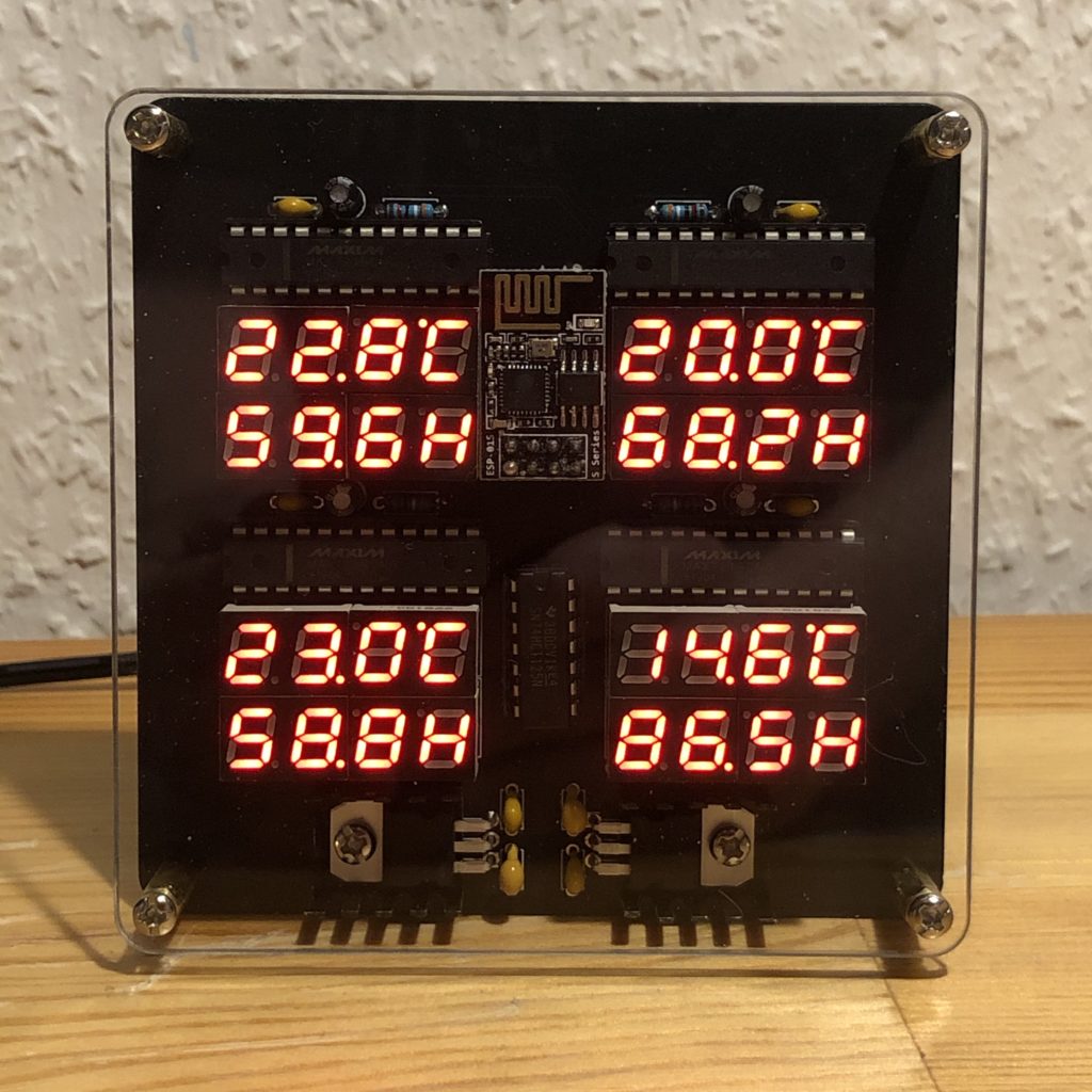
This started as an idea to use some 7-segment displays I had and ended up being another decorative but also very practical gadget…
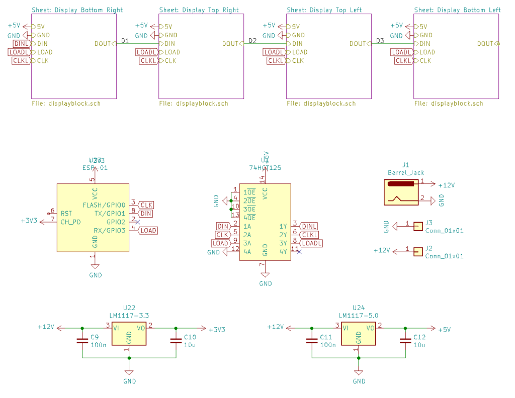
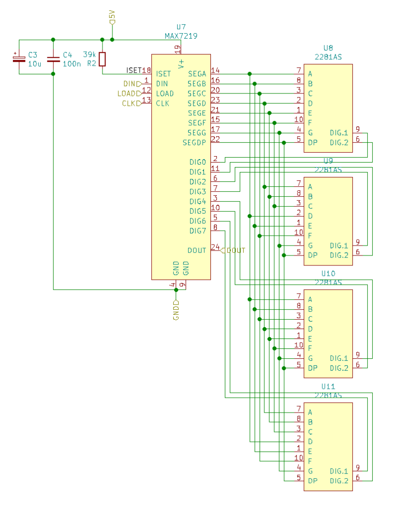
Since I already collect a lot of data including temperature and humidity in different rooms and outside, I wanted to display those as well. My first idea was to have a display for each room, but when I got my paws on some quite small 0.28″ tubes I decided to toss them all on a single board, with one MAX7219 for each room. Since those are the only thing I need to control and I need just three GPIO pins for them I settled on using an ESP-01 this time which is the simplest in the ESP module family and it has four GPIOs available when serial communication is not needed.
The ESP runs on 3.3V though and the MAX7219 needs a 5V input signal to run stable so I needed a logic level converter. I chose to abuse a 74HCT125 for that which can be used to convert up to four 3.3V signals to 5V.
The last but not less important thing was getting power into the board.
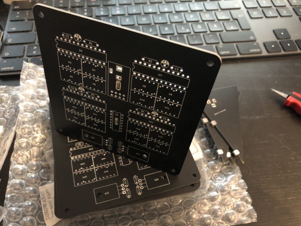
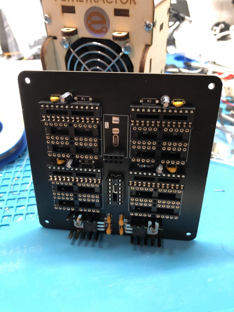
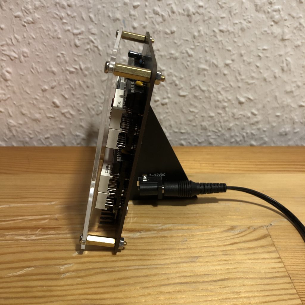
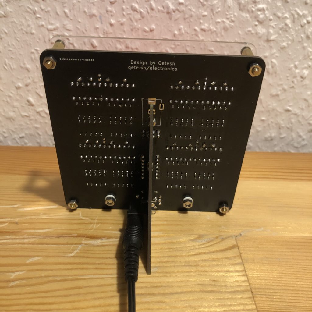
I didn’t want to use USB this time but instead using voltage regulators to create the 3.3V and 5V that I need. And since I again also wanted it to look nice I am using the big TO-220 versions of the LM1117. This was also the first time I designed two PCBs for the same project, though the second one is also the most simple board I ever made. It is just a stand for the main board and holds the power connector. I designed the main board in a way that it can also work on it’s own with an optional place for the power connector when the stand-board is not attached.
Each block is made of four 2-digit tubes, aligned in a way that creates two 4-digit displays each. The second tube of each row is mounted upside down so I am able to use the decimal point as a degrees symbol for the temperature display. One MAX7219 is able to control 8 digits so I need one for each of the four display blocks.

