Since I started adding some automation to my home, I wanted a way to see the status of everything in a single glance when leaving. Not everything is connected yet but most lights are and I started installing door- and window contacts. I got the idea of having a display next to the entrance which tells me everything at once. And since I like visible electronics I started planning a little gadget that is basically just a pcb with LEDs.
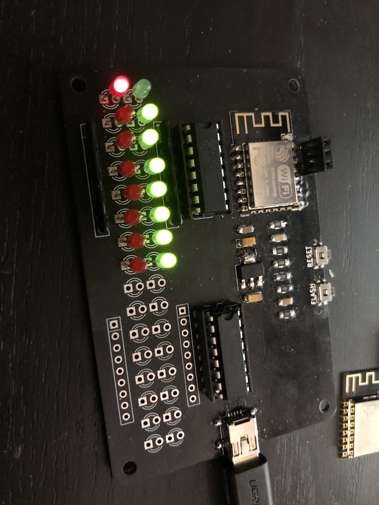
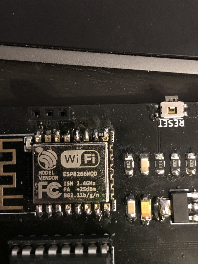
I played around with shift registers before so I knew how to control them with an arduino (Spoiler: It’s extremely easy). But since I wanted the display to be connected to my network I used an ESP based solution. After some prototypes I decided to use an ESP-12F module which basically only needs a proper power supply and a few resistors as external components. Even the wifi antenna is integrated. And it’s cheap!
I wanted the whole thing to be USB powered so I had to add a voltage regulator as well. And since the ESP-12F is using SMT, I decided to make this my first project using more of that technology. Since I never really worked with them I chose the rather “large” 1206 size to have it easier. The first draft of the board still used regular resistors though. I also made a mistake here which I unfortunately only after receiving the boards… I forgot to tie GPIO15 to ground which means that the ESP did not boot correctly – Details are explained here. For my first prorotype that was ok – I just soldered a resistor in between GPIO15 and GND which are next to each other anyway. But since I wanted the whole thing to look good without a case I needed to order new boards after correcting my error.
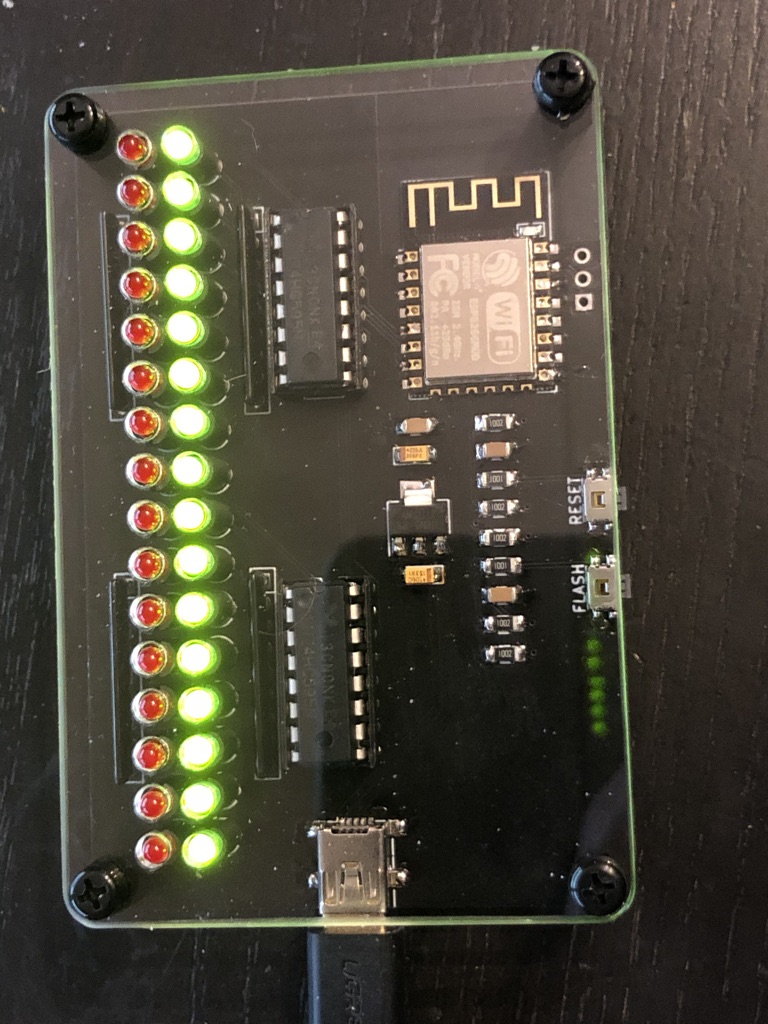
I added hardware debouncing to the buttons because why not and also moved the LEDs slightly to fit into a 5 mm raster because I wanted to protect the board with an acrylic glass cover and that made placing the holes a lot easier.
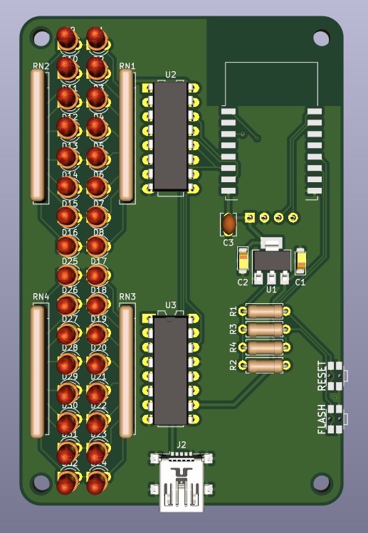
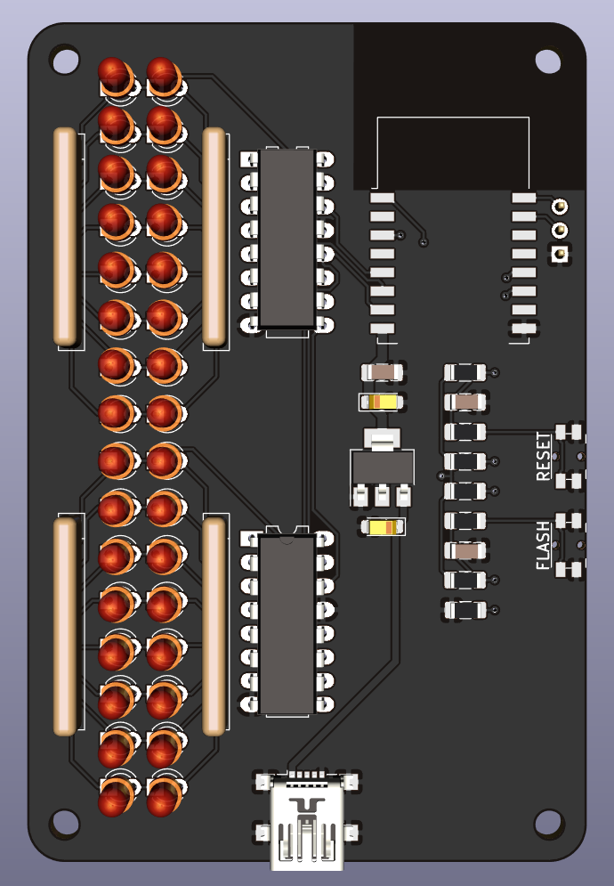
This is the final version of the schematics, made in KiCad:
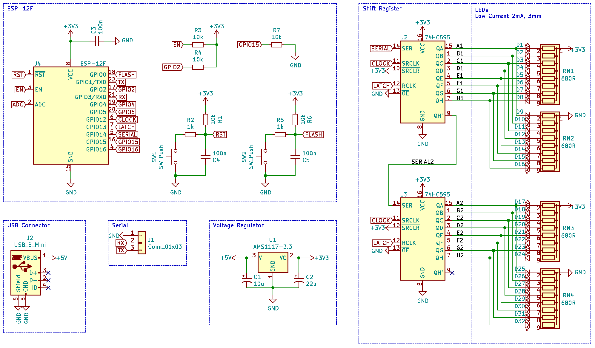
I am using low current LEDs which need just 2mA to light up quite bright since I can run those directly from the outputs of the 74HC595 shift registers. Four resistor networks provide the needed limiting resistors for the LEDs wich are connected in pairs so they light up either on high or low level.
Everything is controlled by a python script running on my home server which collects the data from the different devices in my home and sends a simple string of 1s and 0s via MQTT to the ESP which then feeds those into the shift registers.