This little project had the goal to turn a cheap, simple 230V motion detector into a WiFi-enabled device that connects to the rest of my home since devices that come with built in WiFi are quite expensive. I found a motion sensor that has enough room for my own little board in its housing. It has a built in relay that pulls one of the three wires inside to 230V AC which means that I had to deal with that. I found several ways to achieve that but decided for one of the simplest variants:
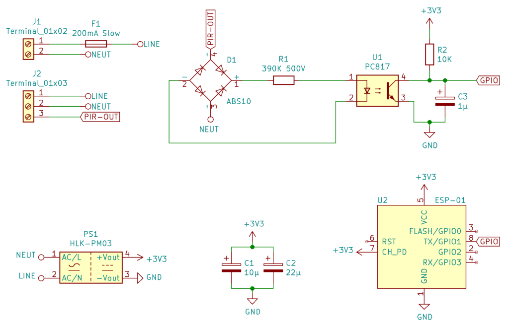
A full bridge rectifier (ABS10 since I have lots of them), a 390kΩ resistor which of course has to be able to handle the voltage and a PC817 photocoupler. The resistor I use is rated for 500 volts which is enough to handle the round about 320V peak voltage it will encounter.
The output of the photocoupler gets a pullup resistor to 3.3V and a smoothing capacitor of 1µF to get a steady signal. Now, as soon as the input gets 230V AC, the GPIO of my ESP-01 will be pulled down. I will come back to this…
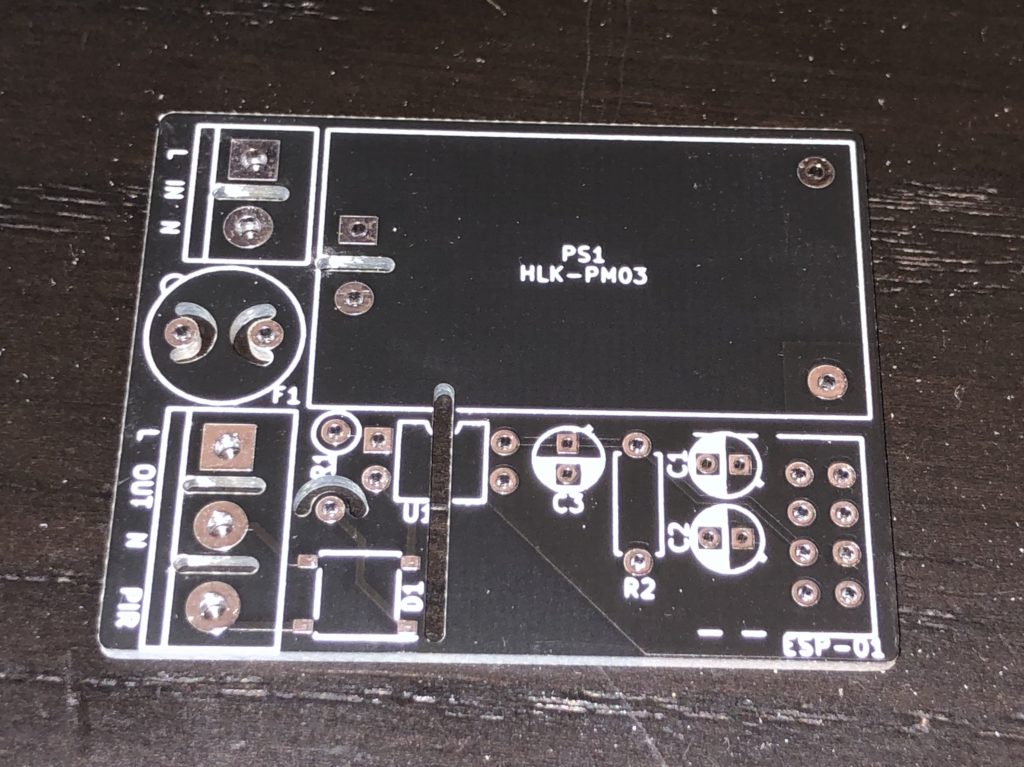
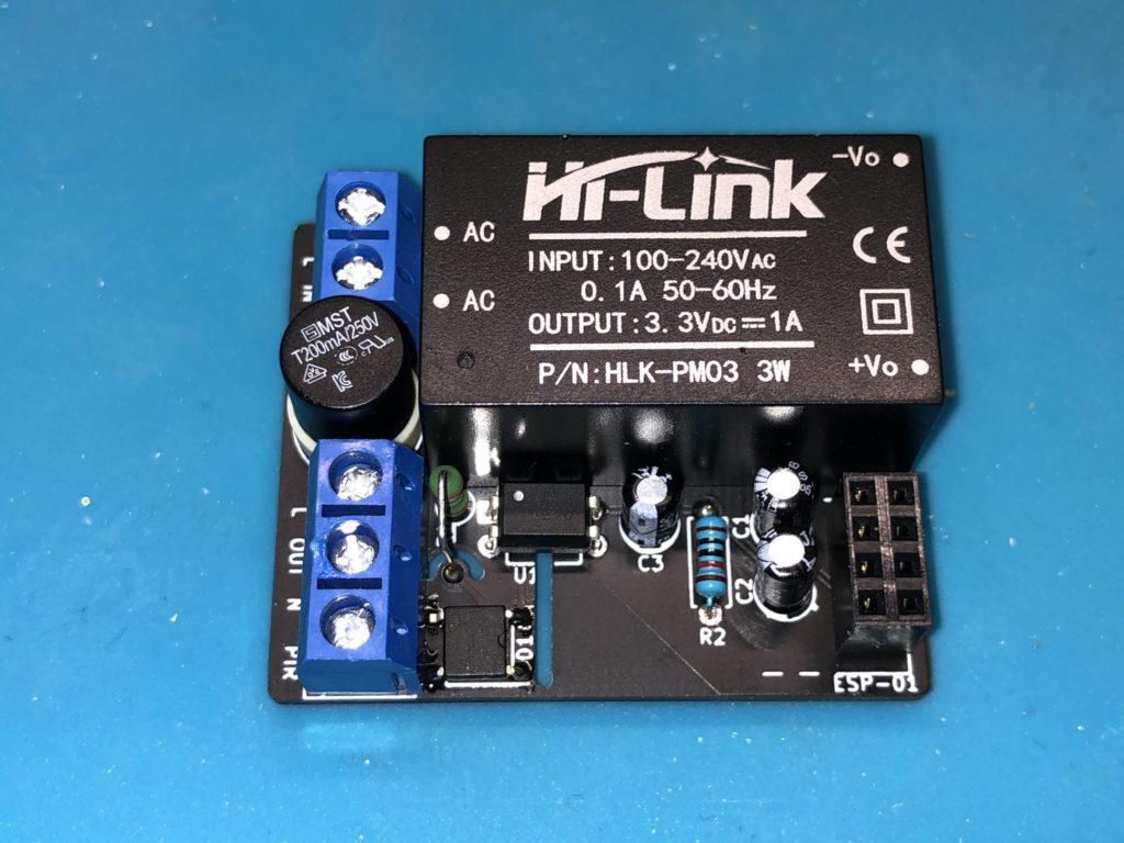
As always, I designed a little board around this rather simple schematic. I am using the very common HLK-PM03 which is a very compact switched power supply with a 3.3V 1A output. Adding a couple capacitors to smooth the voltage for the ESP and a slow blow 200mA fuse on the input just in case completes the setup.
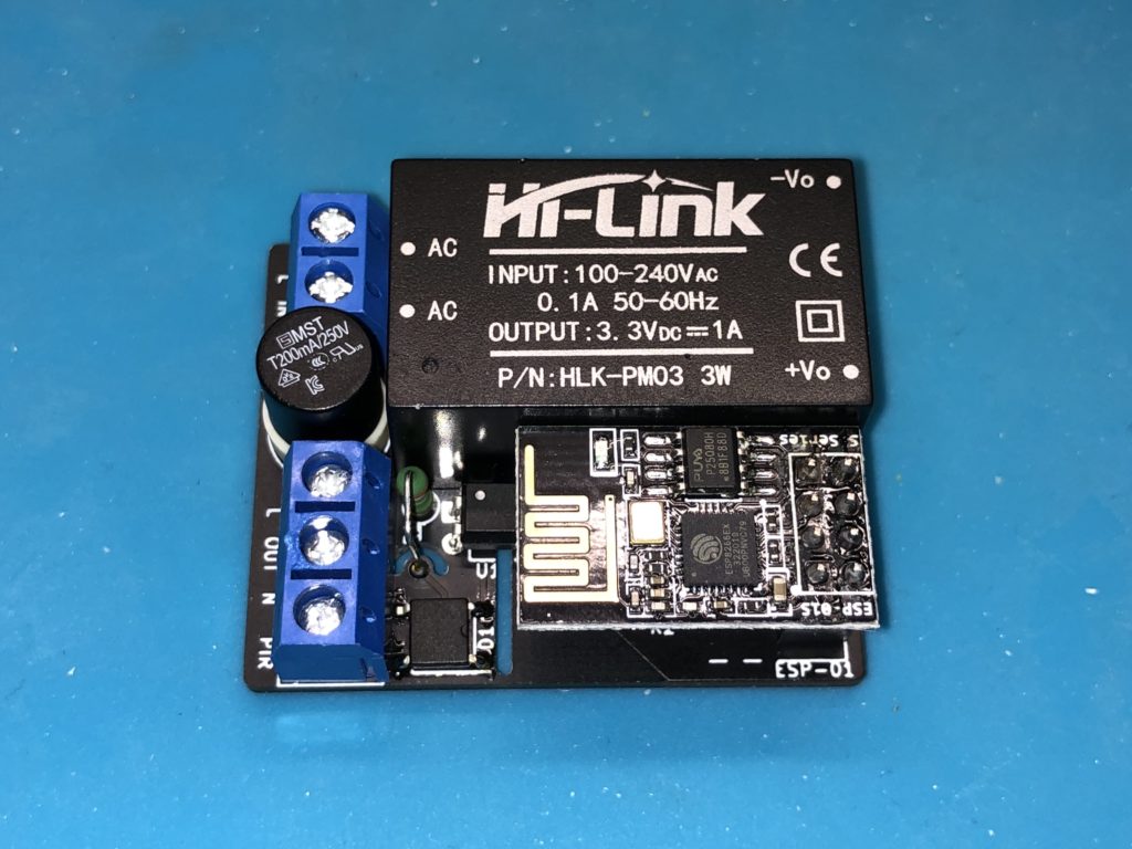
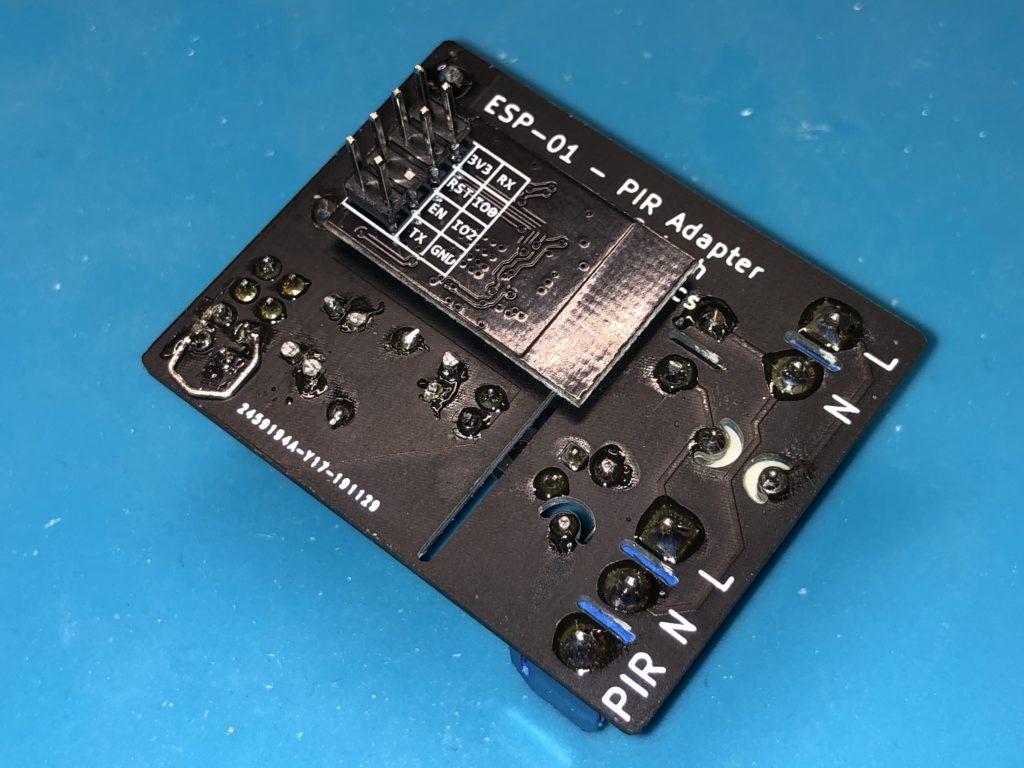
Now, the ESP-01 has two available GPIOs – 0 and 2. Since the built in LED is on 2 I used that one to connect the motoin sensor as it will give me some simple visual feedback. What I did not know when desining this board, is that the motion sensor immidately switches on when it gets power. Which also means that GPIO 2 was pulled down on boot. And since that is part of the boot mode configuration my little device failed miserably the first time I powered it on. The ESP would not boot anymore. I am sure at some point I will learn to not make this kind of mistake. But in this case it was at least easy to fix by cutting of the GPIO2 pin of the ESP and soldering a little wire between two pins to connect the motion sensor to the serial TX pin which is also GPIO1 and can be used as long as no serial communication is needed – and that one is not used by the bootloader.
Of course I already fixed that mistake in my schematics and if I ever order more of these boards they will be correct. For now I am fine with the fix since it won’t be visible once mounted…
After everything worked as it should I flashed the ESP with Tasmota which makes it extremely easy to integrate the motion sensor into my home automation and which is running on several other ESP based devices here by now.