Based on the Oscilloscope in a Matchbox by Peter Balch
Last Update: 2019-01-03
I found this project in a reddit post a while ago and I loved the idea. I wanted an oscilloscope for quite a while but what I actually needed was mostly something to check if there’s a signal at all. This little project seemed perfect for the task and since I just started working with KiCad I decided to turn it into a board.
After recreating the schematics in KiCad I got the idea to make an Arduino UNO shield since I had a few Arduinos in my drawer anyway. I ordered the parts I still needed and started designing the board. It actually took a few iterations to decide on a final design but here is the result:
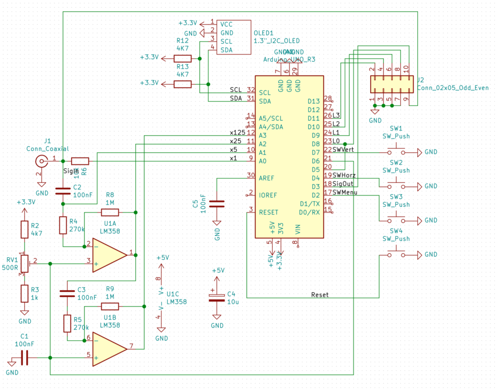
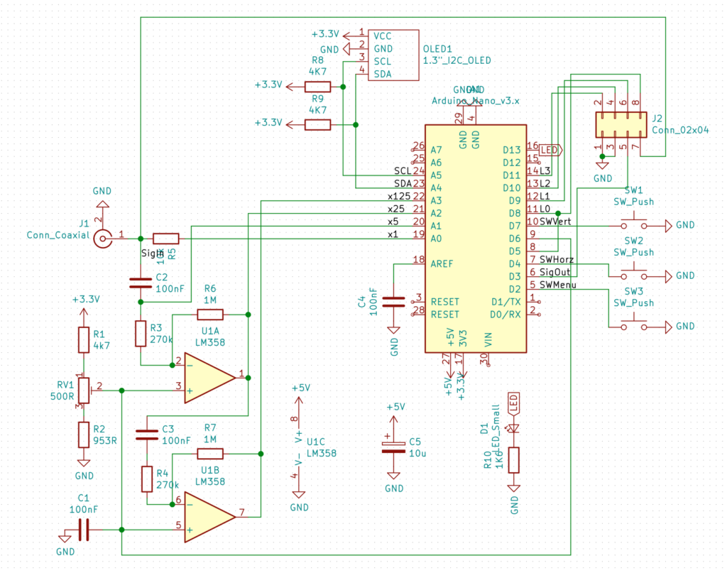
My version of the schematic design 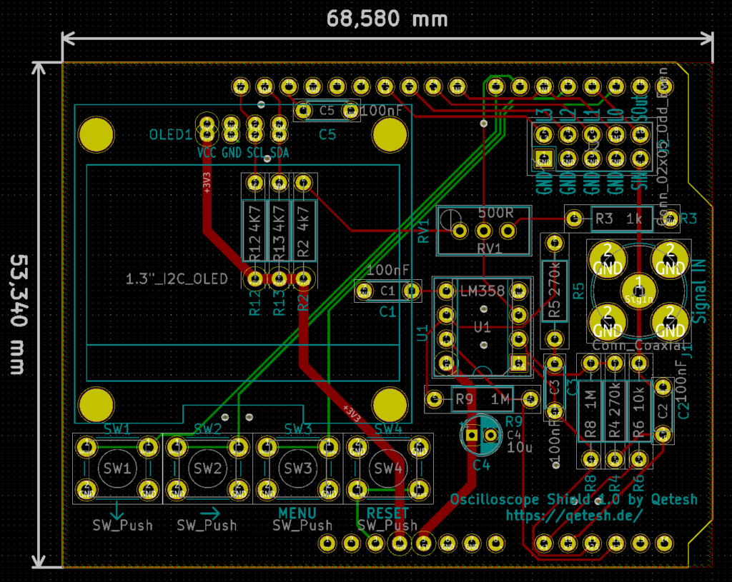
PCB Design in KiCad 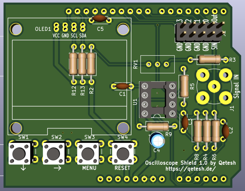
3D-Render
I made a few changes from the original project:
- The Arduino UNO has less analog inputs than the NANO so the voltmeter was removed
- I had no use for a signal generator (yet) so that got omitted as well
- Two more buttons were added, one to enter and exit the menu and one to reset the Arduino as the original reset button is covered by the shield.
The menu button is connected to pin 2 on the Arduino which was used for the signal generator by Peter - R9 in the original schematics was replaced with a trimpot to be able to fine tune the AC display without resoldering
- A BNC connector was added to the signal input so a probe can be connected easily
- All in- and outputs were combined into a single 2×5 header with 4 ground connectors because you can never have too many of those
- The code was changed a little bit to add the functionality for the menu button and the timeout for the menu was removed. Everything else is still Peters original code.
All files can be downloaded here. Feel free to use them for your own projects. I publish these under CC BY-NC-SA 4.0
Version 2.0
Schematic design for Version 2.0 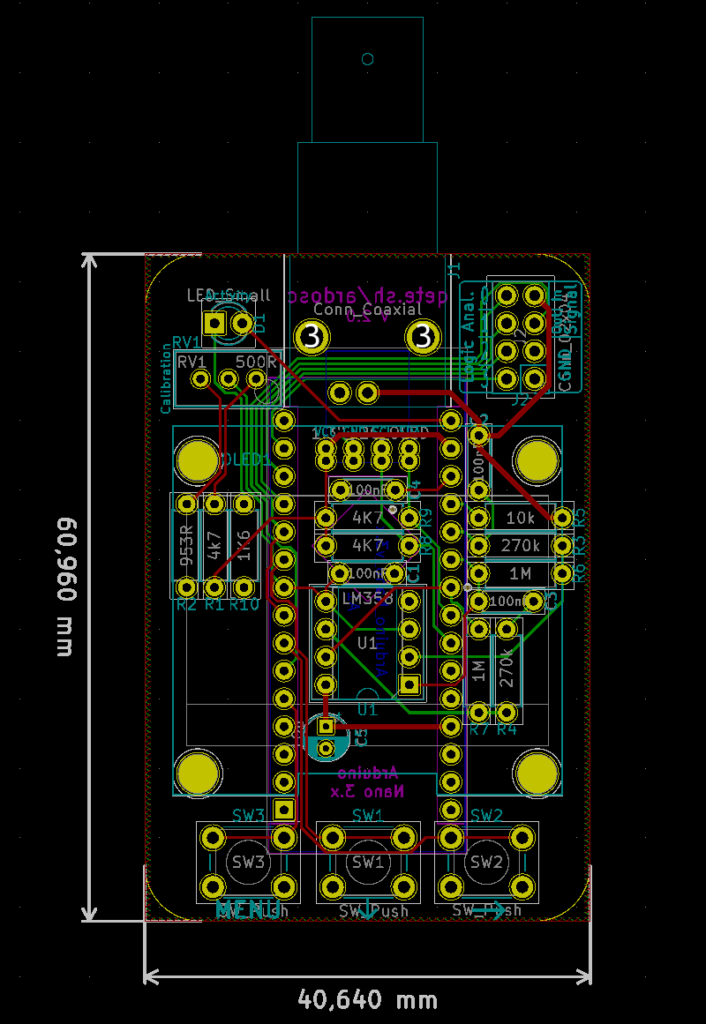
PCB Design 2.0 in KiCad 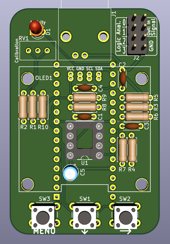
3D-Render 2.0
Version 1.0 was was still too big. When Peter made the original design it was based on an Arduino Nano which of course is a lot smaller than the Uno. I chose to make an Uno shield at first because I had spare Unos – But then I thought I should try to make it smaller. Maybe even smaller than Peters original version?
I wanted to keep the extra button and also the BNC connector but I replaced the latter with a horizontal one as the vertical one is kinda annoying because the cable is always in the way.
After playing with a few different designs I decided for a vertical version. A friend offered to design a 3D-printable case for it so that will hopefully be available as well at some point!
Everything else is basically still the same. I just moved stuff around, most of it under the display – in the first version that was mostly dead space. Also fitting everything around the contacts of the Nano was a nice little challenge but I think I got quite good with this kind of puzzle by now and the board turned out very neat and tidy in my opinion.
All files for version 2.0 can be downloaded here. Feel free to use them for your own projects. I publish these under CC BY-NC-SA 4.0
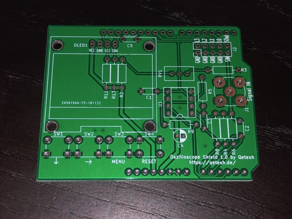
V1 PCB Front 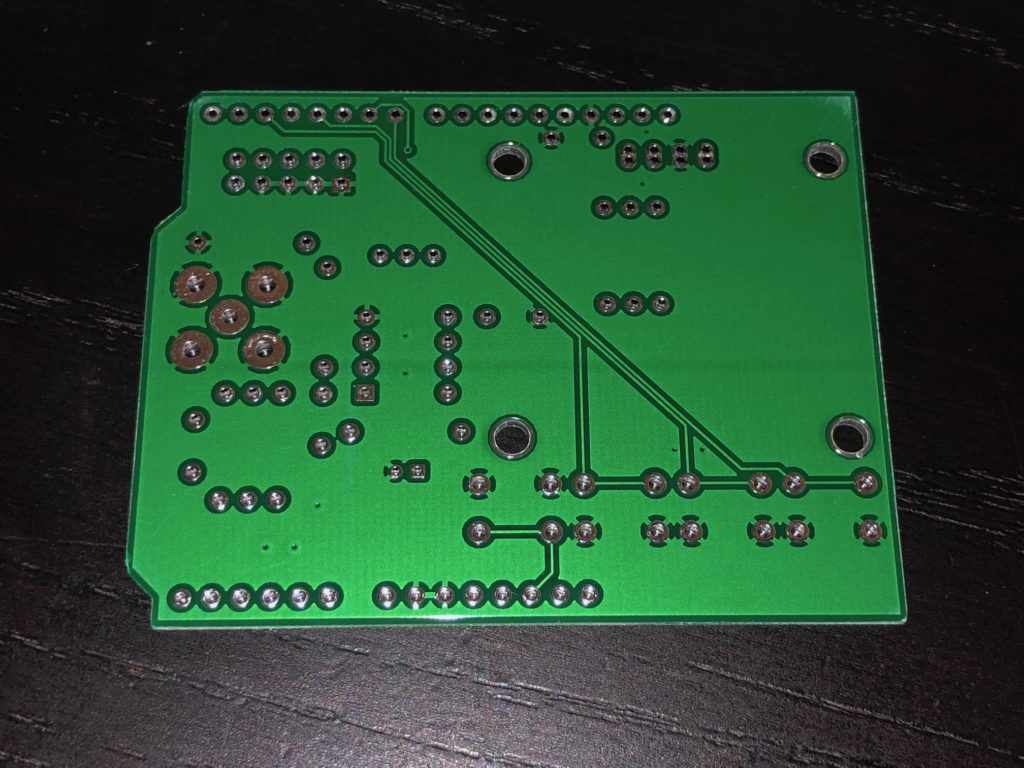
V1 PCB Rear 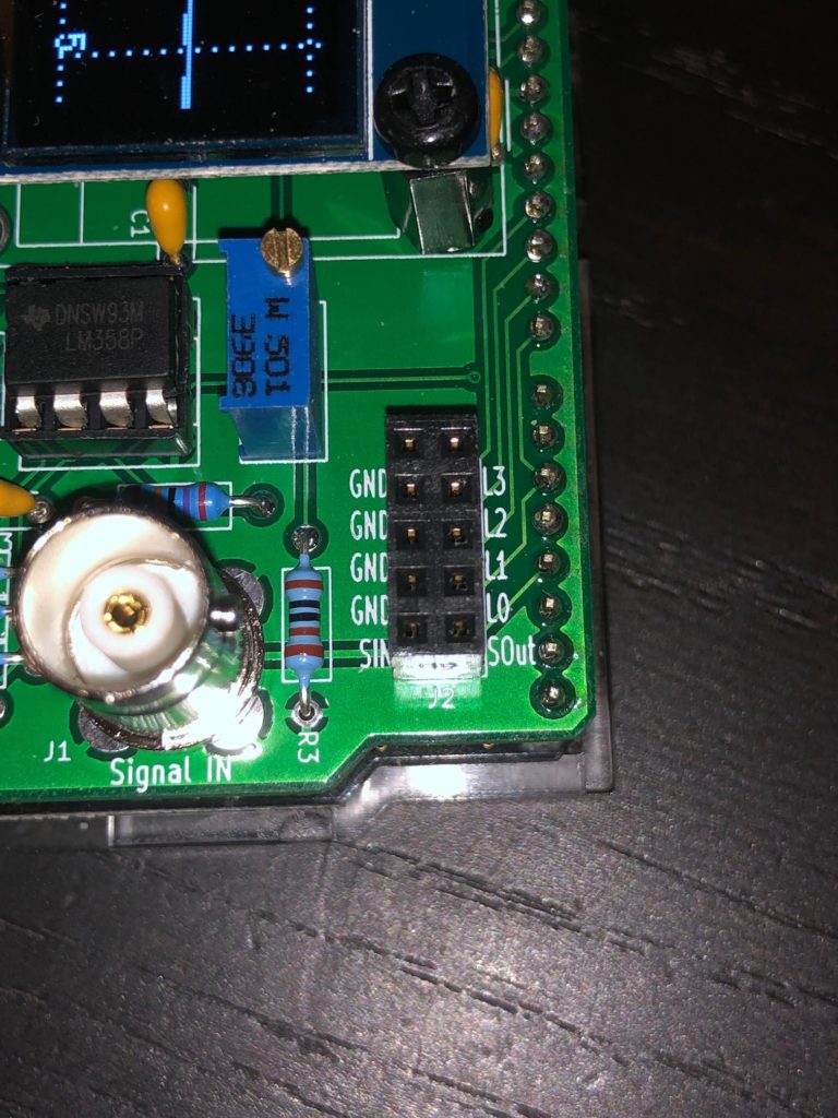
V1 Header 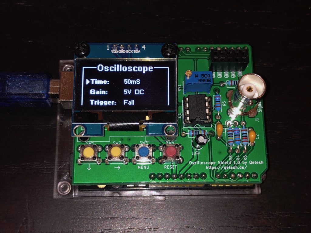
Menu 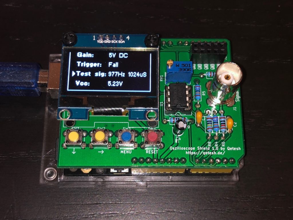
Menu 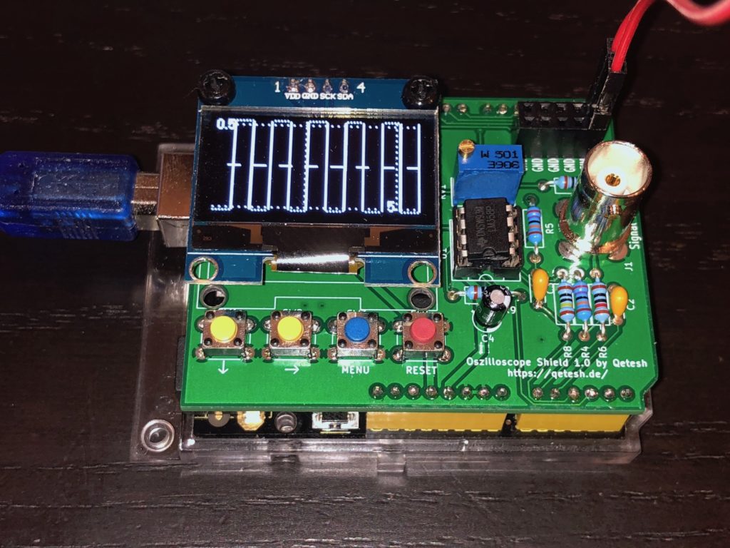
Test-Signal 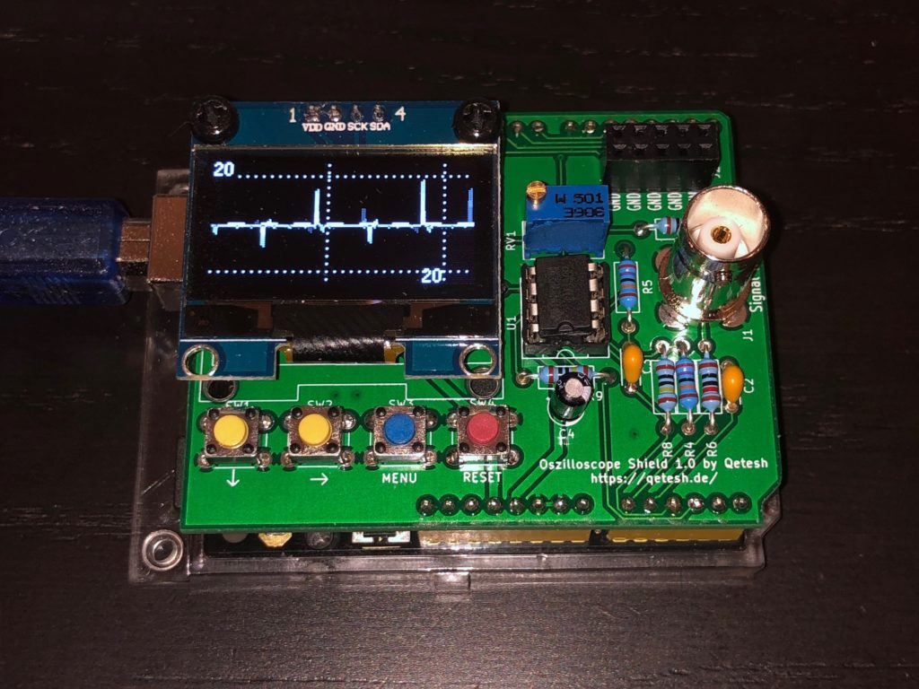
Floating Input 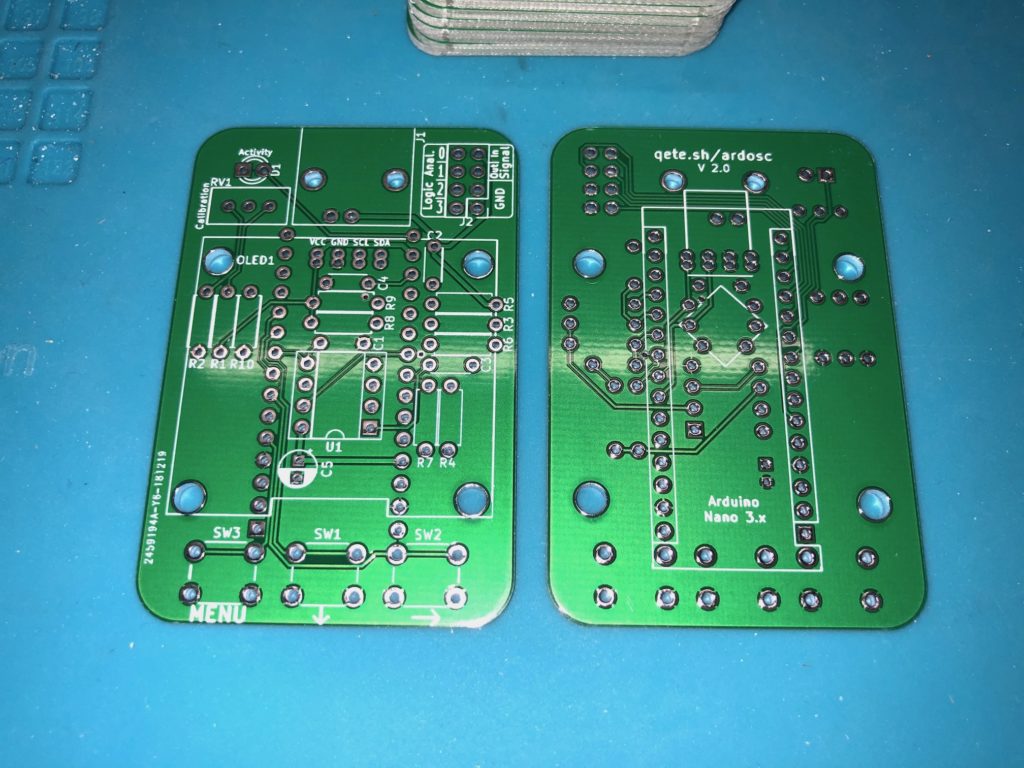
V2 PCB 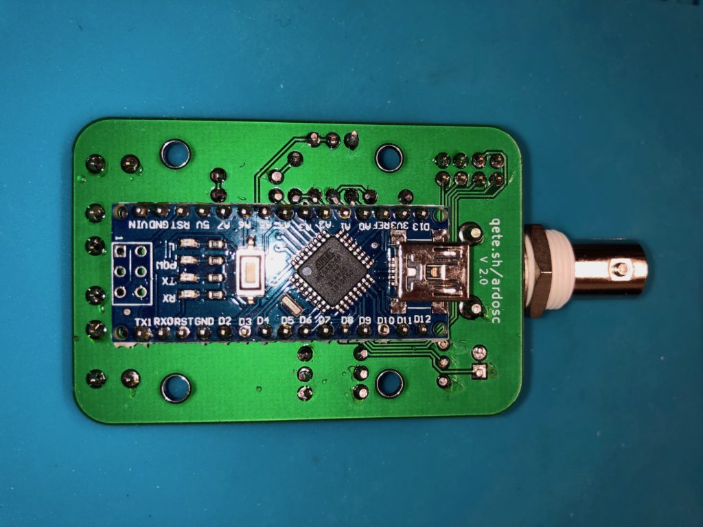
V2 Soldered Bottom 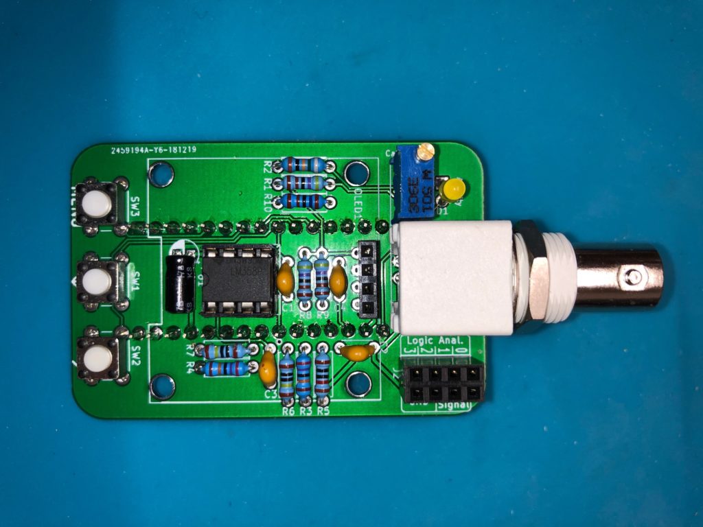
V2 Soldered Top without the display 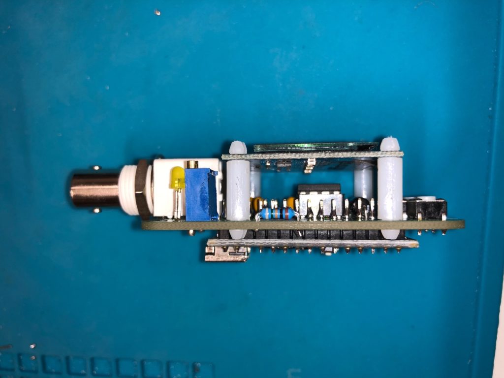
V2 Side View 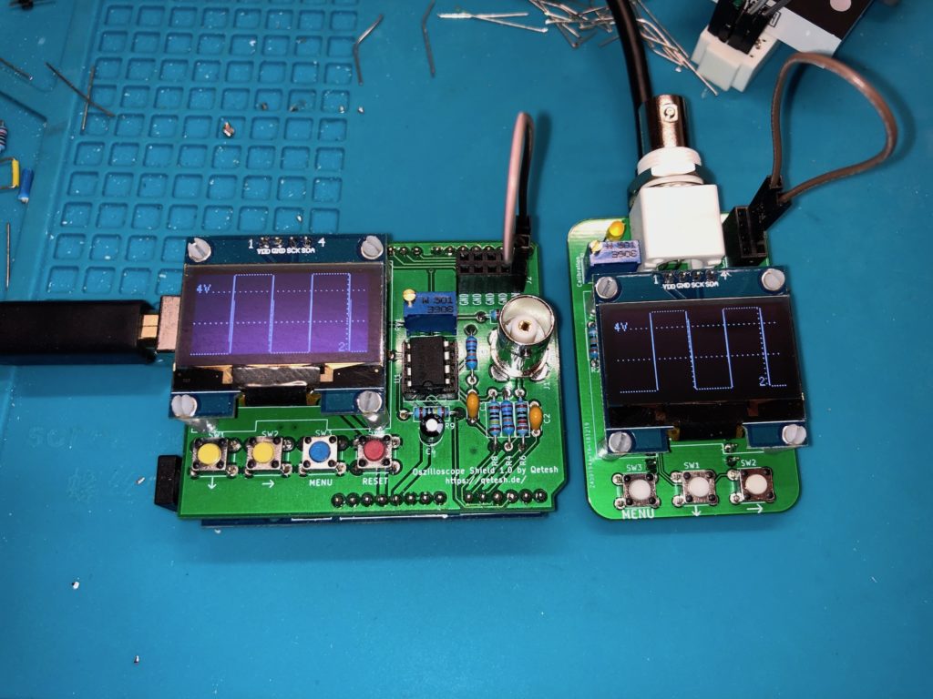
Comparison between V1 and V2
Yes i have also made it.
I can’t upload pictures, here. Sorry, but build in a small measuring probe case. With a Arduino pro-mini.
Works good, but it can be optimized. The debounce of the 3 keys is not so good.
Frequentie measurement dosn’t work.
And i am missing the Voltmeter function. It must be in the software.
But nice made. If my case is still deliverable than a print would be nice.
Greeting for the netherlands.
He said he omitted the voltmeter and signal generator. I’ve built both of these and are very happy with them.
I’ve tried to design a 3d case, but not successful.
Got my pwbs from JCLPWB today and built one. Burned out the Nano before I found your 1.3″ OLED has vcc and gnd reversed from mine. Don’t see and easy way to reverse them other than leave the pins out and use wires. More later.
used wire for vcc and gnd and put a 9v battery clip on Vin and Gnd. Runs great off a 9v Battery. Wish I had a 3D printer to make a case for it. 🙂
Did your friend ever come up with a case for it?
Did anyone come up with an .stl for a case for this scope? I have a 3d printer now, but not very good at design.
Unfortunately not, sorry. I would have published it here, if there was one… But if you already have a printer you should tinker with design, too! I got fairly good at it by now with lots of practice…
Like these?
https://smile.amazon.com/gp/product/B072WQZHLD/ref=ppx_yo_dt_b_asin_title_o00_s00?ie=UTF8&psc=1
Thanks,
Joe
They look correct, yeah!
If you don’t sell them, could you explain how to go about getting them made?
Thanks
I do not sell them since, unless you live in Germany, shipping them would cost more than producing them but you can download the Gerber files from this page and have them produced by any pcb manufacturer, then solder them yourself. I got these made by JLCPCB but that’s just one of the many options you have.
Ok…Just did my first order with JLCPCB with your ver 2 gerber files. Question: supplier/part no. for the BNC connector?
Thanks
Also, Eagle wont open the schematic. Do you have it as a pdf maybe?
Thanks
Well, just stumbled on KiCad site…Yep! All OK!
I used these from Reichelt, I assume you’ll have to find your own supplier but they are fairly common. https://www.reichelt.de/bnc-printeinbaubuchse-gewinkelt-50-ohm-ug-1094w1-p22018.html
Do you sell your pcb’s?