We got a used WatchGuard Firebox M400 which we plan to use as a home router. After replacing the loud original fans with silent ones and the old, slow Celeron G1820 with a more modern, a lot less power hungry and much faster Core i3 4370T, there was one little problem: The box couldn’t reboot anymore. Booting is fine, shutting down is fine, but when doing a reboot the box hangs at the POST – The same happens for other people as well and there seemed to be no solution – until now!
I noticed that while hanging in this state a few LEDs were lit on the front panel, including the status LEDs for the SFP cages. Since we don’t use those, I took some measurements to find the best place to hook into those and started designing some hard- and software. I don’t know how the SFP LED acts when a module is installed but the software I wrote only reacts if the LED is on constantly for more than a set time so as long as it would never be constantly on it might even work with the cage in use. Or you try to find another point on the board that works to detect the hanging state – I would have prefered to not use the LED for this and poked around with the oscilloscope but I wasn’t able to find another point that behaves the same.
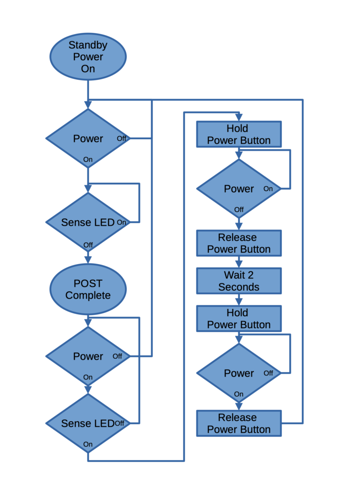
The flow chart on the right shows how the tool works. Once it’s powered it uses the detection of 5V on the power supply and the state of the sense LED to wait for the POST to be finished since it is also lit in this state. It then goes into an internal standby mode where it constantly checks if the Firebox is still powered and if the sense LED is lit for more than a few seconds. When the box is just powered down it goes back into the POST waiting state. If the sense LED is lit, the reboot sequence is activated where it holds the power button until power is off, waits 2 seconds and then powers the box back on, at which point the cycle starts again.
I am just using an ATtiny85 (a 25 or 45 would work as well but I have enough 85s around), a FET to level-shift the voltage from the LED cathode to 5V, the 5V line of the power supply and another FET to “press” the power button. I also use the 5V Standby line to power the microcontroller so it can run while the box is switched off. I added a few LEDs for debugging and that’s it. After writing some software using Arduino it was already done and now the box can be remotely rebooted without problems. It takes a few seconds longer but at least it works!
The connections that have to be made in the firebox are as following (Firebox -> Rebooter):
- Power Supply Ground (Black) -> GND
- Power Supply 5V (Red) -> PSns
- Power Supply 5VSB (Purple) -> +5V
- SFP LED (LED3 C1) -> LSns
- CONN1 (next to RAM) -> Power Button
- The original power button cable that goes to the rear of the box can be connected to the second Power Button connector on the Rebooter to keep it functional
I used original Würth WR-WTB 2.54mm plugs for the power connectors since that’s what used in the box as well, but simple header pins should work as well. The FETs used are Si2302 (again, because I have lots of them) but I am quite sure that any logic level N-FET in SOT23 works. The LEDs (and Q3) are optional but useful to see if everything works as planned.
All files, including hardware sources (KiCad), Ready-To-Order-Gerber-Files and the code for the ATtiny can be found on my GitHub!
Also, because I have to say this: If you use my files to build your own Firebox Rebooter, keep in mind that, while I have built and tested this myself and it works here without any problems, I take no responsibility for any damage this modification might cause to your hardware! You do this at your own risk!
Have a few pictures:
Overview 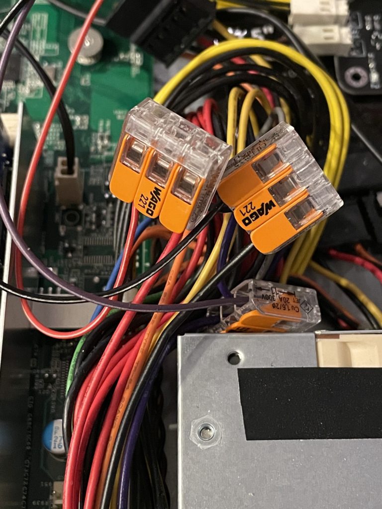
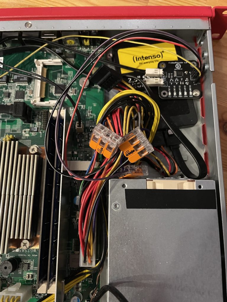
Connections made to the power supply cable 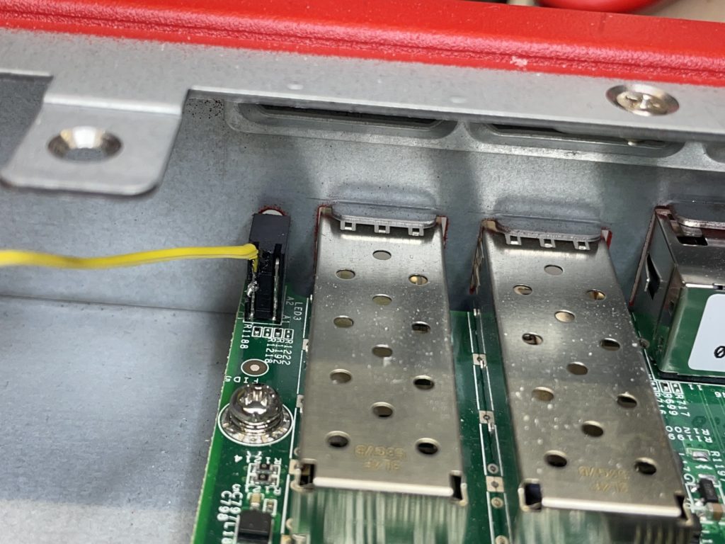
The sense cable soldered to the SFP cage LED 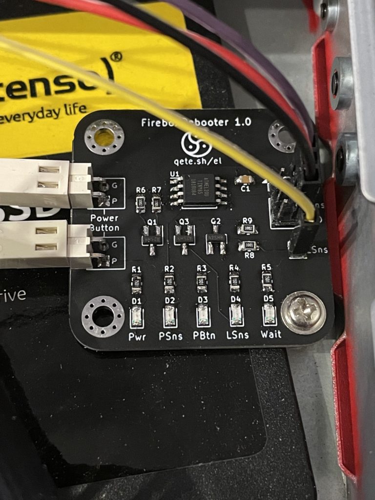
The installed FireboxRebooter