I always wanted an Xserve for my Server Rack just because I think they look awesome and I am an Apple fanboy… So when a friend had a broken one I made grabby paws! After hauling it home I started looking into turning it into a decorative object – I wanted it to light up as realistic as possible without investing too much. Inspecting it’s guts showed that all the front LEDs are basically controlled by two boards: The front panel board which controls the buttons and the LEDs plus the harddrive backplane which controls the HDD cages.
The hardest part was reverse engineering the 34 pin front panel connector and the 12 pin HDD backplane connector without damaging anything. With lots of patience and measuring I figured the pinouts out though – Just in case anyone needs them:
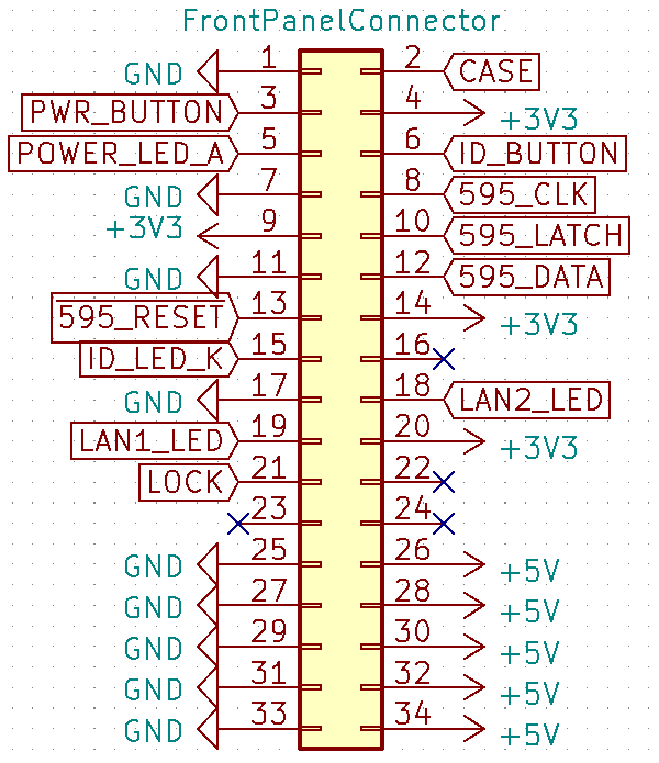
- Pins 1, 7, 11, 17, 25, 27, 29, 31, 33: GND
- Pins 4, 9, 14, 20: +3.3V for the logic components (All components that I was able to identify are 5V compatible according to their data sheets in case you want to use a 5V logic level to control the front panel but I did not test this!)
- Pins 26, 28, 30, 32, 34: +5V power for the LEDs – These pins needs to be switched in case you want to disable everything
- Pin 2: Case sensor, needs a pull-up resistor to 3.3V and gets pulled down when the case is closed
- Pin 3: Power button, gets pulled to GND when pressed
- Pin 5: Power LED anode, I am controlling it with a P-Channel FET on the 5V rail and a 30Ω series resistor to limit current
- Pin 6: ID Button, gets pulled to GND when pressed
- Pin 8: 595 shift register CLOCK signal
- Pin 10: 595 shift register LATCH signal
- Pin 12: 595 shift register DATA signal
- Pin 13: 595 shift register RESET signal
- Pin 15: ID LED cathode, I am using an N-Channel FET to pull it to GND with a 150Ω series resistor to limit current
- Pins 18 & 19: LAN LEDs, they are switched through FETs on the front panel and these are the gate inputs
- Pin 21: Status of the case lock switch, 3.3V when unlocked, 0V when locked
There are two LV595A shift registers in series (Pins 8, 10, 12, 13) that each control one row of 8 CPU load LEDs
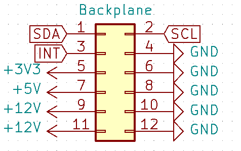
- Pins 4, 6, 8, 10, 12: GND
- Pin 5: 3.3V
- Pin 7: 5V
- Pins 9, 11: 12V
- Pin 1: SDA
- Pin 2: SCL
- Pin 3: INT
Pins 1 & 2 are the data and clock lines for the I2C bus on the backplane. These control four PCA9554 I/O expanders, one for each HDD cage and the 4th one with it’s interrupt pin connected to Pin 3 on the connector to inform the system about changes. There are also two LM75 temperature sensors connected to the I2C bus that measure the incoming air temperature. I was able to identify all pins needed to read the state of the HDD cages and control their LEDs:
- I2C 0x20, 0x21 and 0x22 are each connected to one of the HDD cages
- Bit 0 controls power for the harddrives, I modded the cages so this pin controls the blue LED which is normally directly controlled by the SATA controller in the cage
- Bit 1 controls the red LED
- Bit 2 controls the green LED
- Bits 3-7 should be left as input to not cause problems
- I2C 0x24 is the 4th I/O expander which pulls the INT pin low to inform the system about changes in the HDD cages
- Bit 0: HDD 1 inserted
- Bit 1: HDD 1 locked
- Bit 2: HDD 2 inserted
- Bit 3: HDD 2 locked
- Bit 4: HDD 3 inserted
- Bit 5: HDD 3 locked
- I2C 0x4D and 0x4E are the LM75 temperature sensors
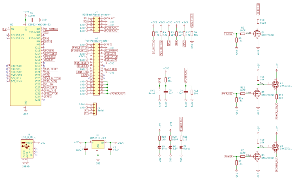
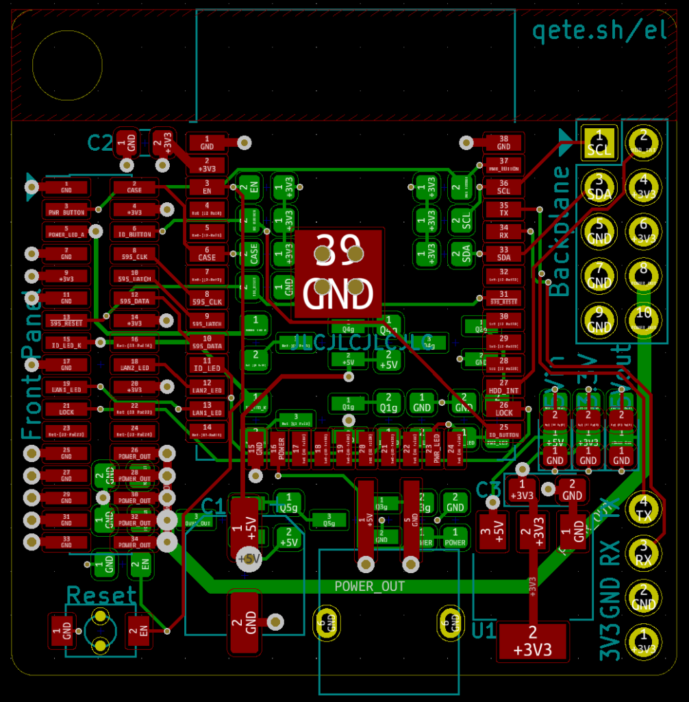
With all this information I designed a controller board, based on an ESP32-WROOM-32 which has enough I/O to control everything in the front panel and the HDD backplane. A small, second board serves as an adapter to connect the backplane cable. Since most of the work is done in software, the schematics of the boards are not that complicated…
I have a few boards left over since I only have one Xserve so if anyone might be interested in building something similar I would be willing to give a few away! The software still needs some polishing but in general it works and does what it should.
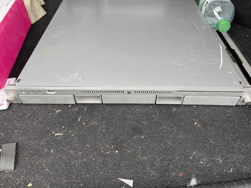
The server as I got it 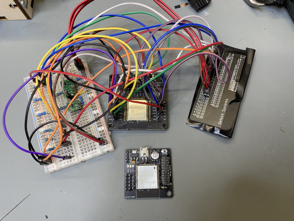
Prototype which was also used to develop the software vs the finished board 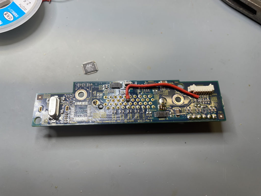
Modification on the HDD cage board – removed the SATA controller and added a bridge between the power control pin and the LED connector 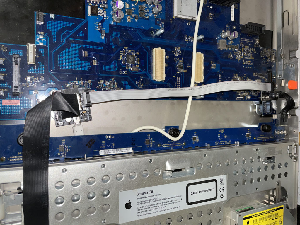
New hardware installed. I removed most of the original guts to make room 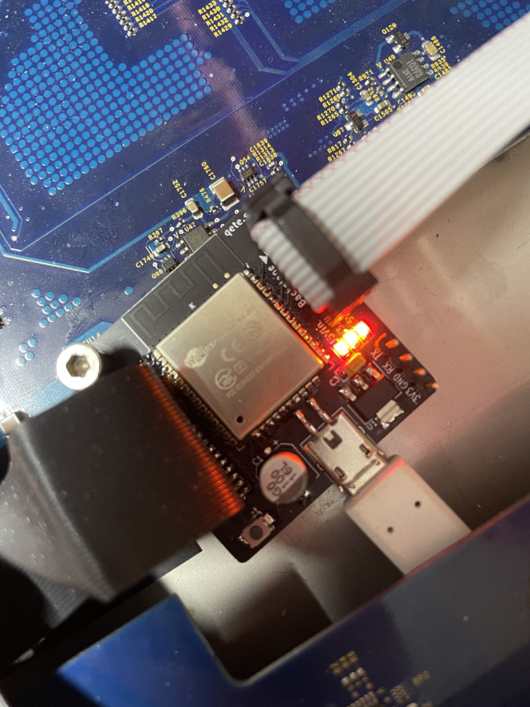
Logic board 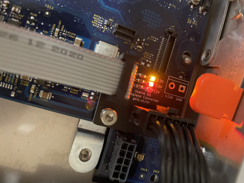
Backplane connector board