It all started when I found a cheap “stack-light” while browsing AliExpress… Back then I had no idea what to do with it but I wanted one. Just for fun. Because I can…
Way too many of my projects start like this…
When it arrived a few weeks later I started thinking where I could mount it and what to actually do with it. Since those lights are usually controlled by some machinery I needed my own controller for it. The light is rated for 12V to 24V DC – Some playing around and blinding myself later I decided 12V is definitely enough. Each of the five lights has its own voltage regulator but they still change brightness a lot when run on different voltages. I also tried running it with PWM and that actually worked so I wanted to make use of that as well to be able to dim them further.
(Next to metric ruler)
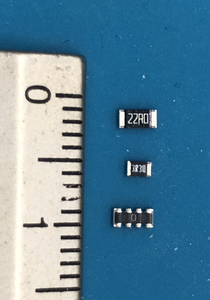
My circuitry is actually quite simple since most work is done by the ESP-12F and I am using a buck regulator module to provide the 3.3V for that one. Five of the GPIOs each control a Si2302 MOSFET to run the lamps, the other four available GPIOs are used to control the LEDs in the case – When I designed the circuit I wasn’t sure yet what to use the LEDs for. Since I needed quite a lot of resistors I decided to try something new: SMD resistor networks, with 4 resistors in a 1206-sized case. Soldering them worked quite well with a heat gun and lots of flux, but I am not sure yet if it’s worth the effort for future projects. It definitely saves a lot of space though!
I decided to mount the light to the fusebox that’s running my server rack so the whole device had to fit into a DIN rail case. I also got a fitting 12V 15W power supply (Mean Well HDR-15-12) and already had a slim switch to be able to cut the power if needed.
As always the board was designed in KiCad though this was the first time it let me down – at first the footprints for the resistor networks didn’t seem to work correct since the soldermask wasn’t applied correctly in the gerber files. Apparently that was working as designed though since I found a solution online: The minimum width for the solder mask has to be changed for such a small footprint. After that everything worked fine and I ordered the boards. Just a pity that KiCad has no function that warns you. If I had not spottet the missing solder mask between the pads, the boards would have been useless.
Once I got the boards and I had everything assembled I installed the software, added the new hardware to the fusebox, connected everything and it worked! Now I just need to find things to display with my new lights.
Oh… and while at it I also added a proper earth connection to the fusebox, too…
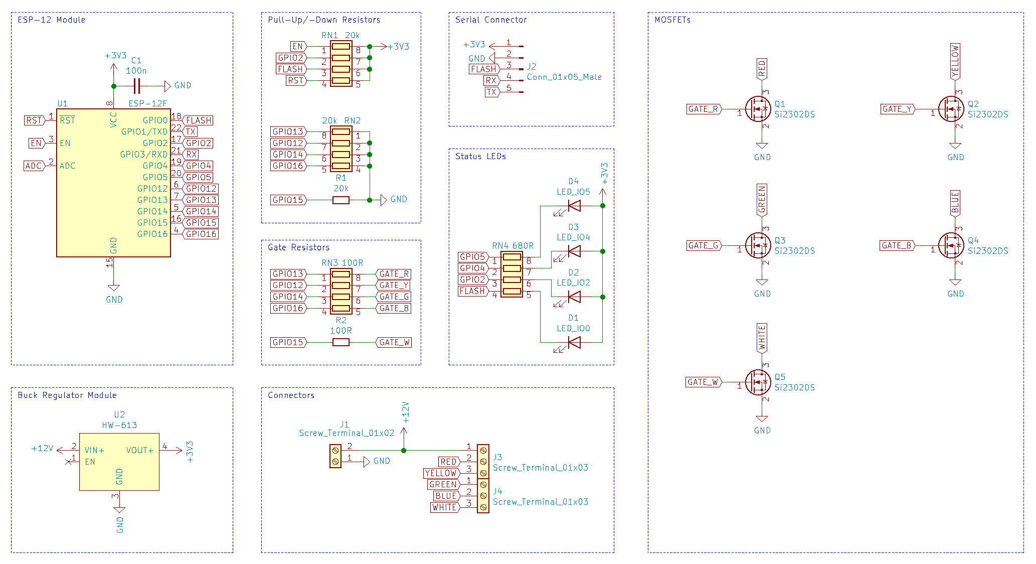
Schematics 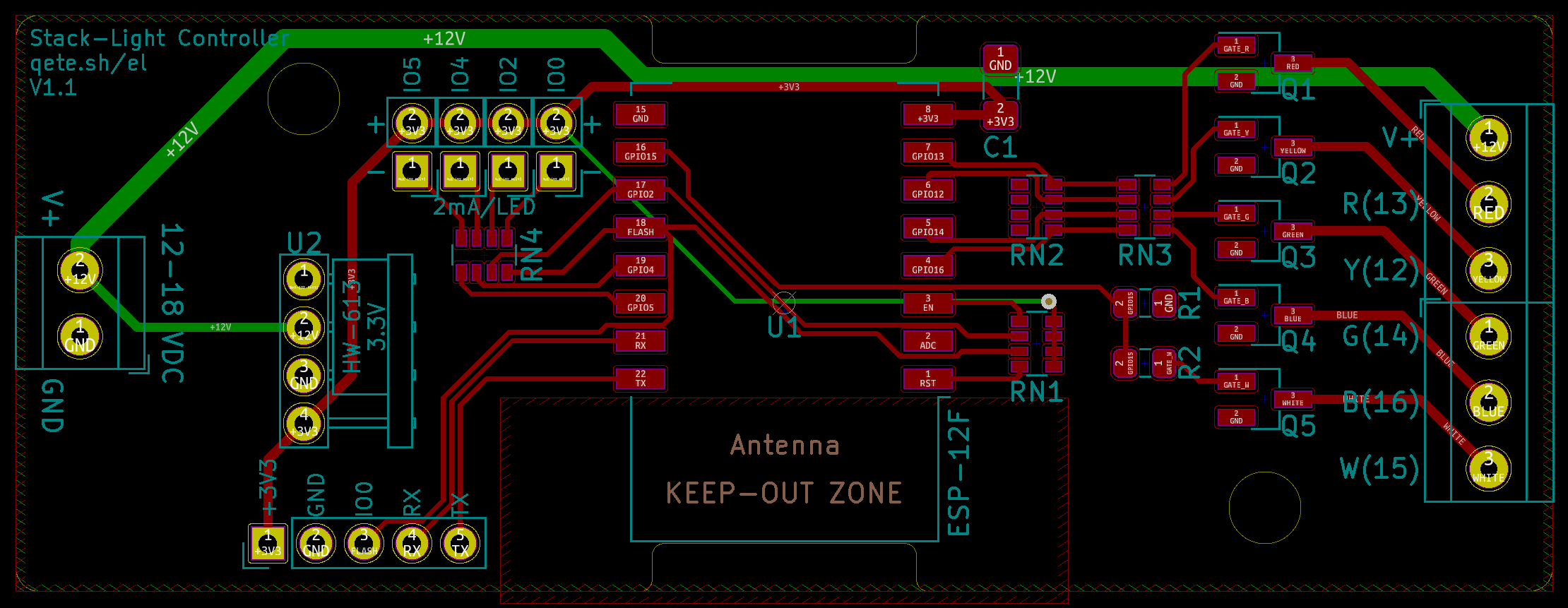
Board Design 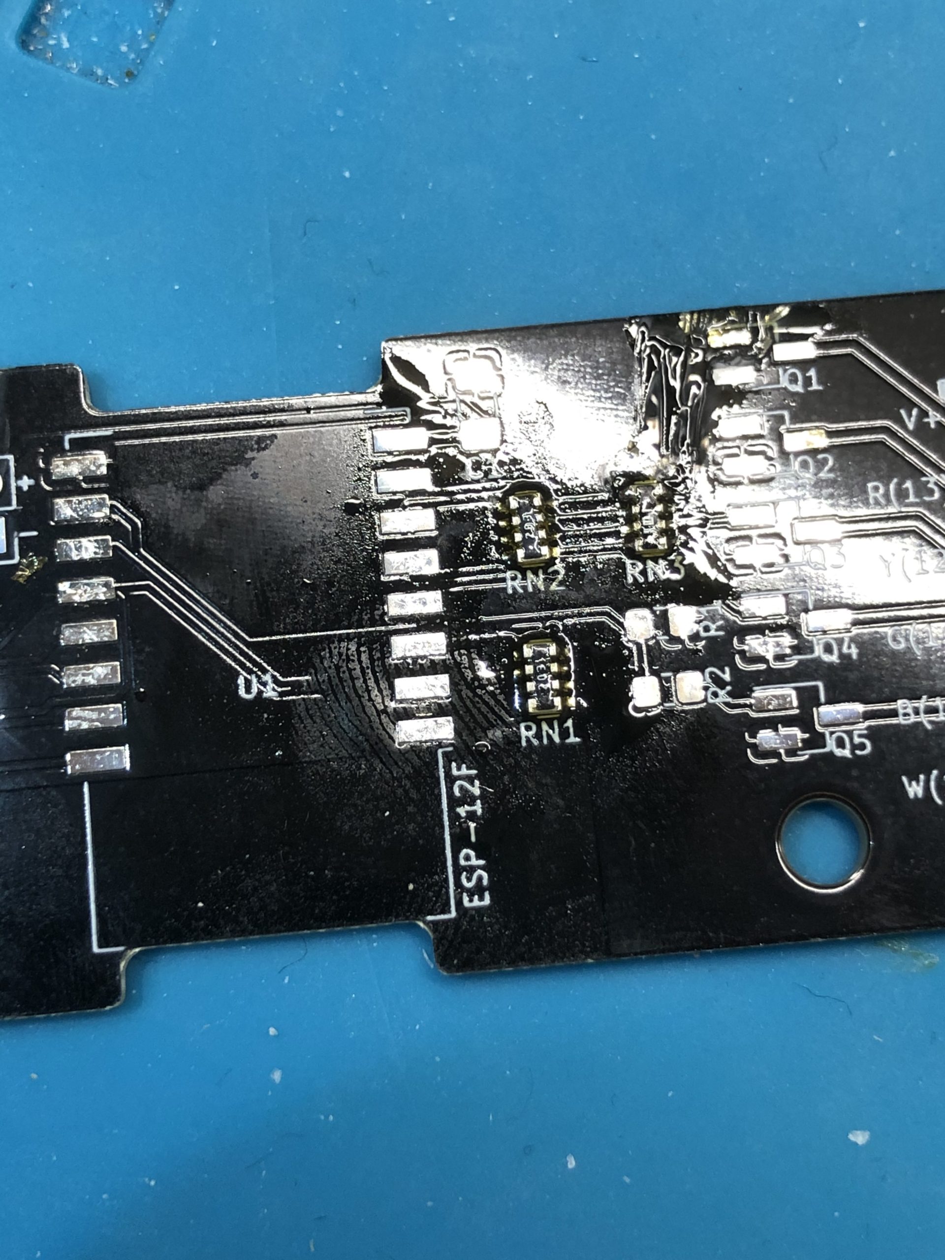
Resistor Networks in place 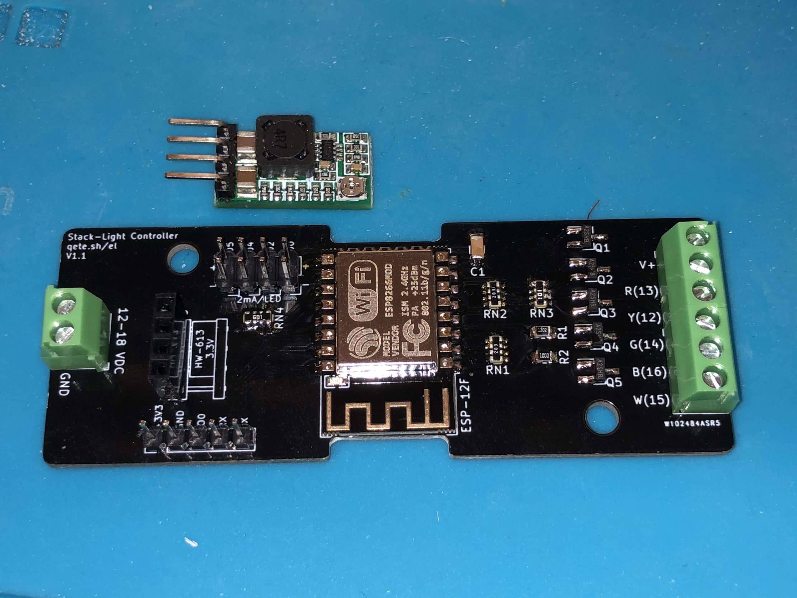
All soldered 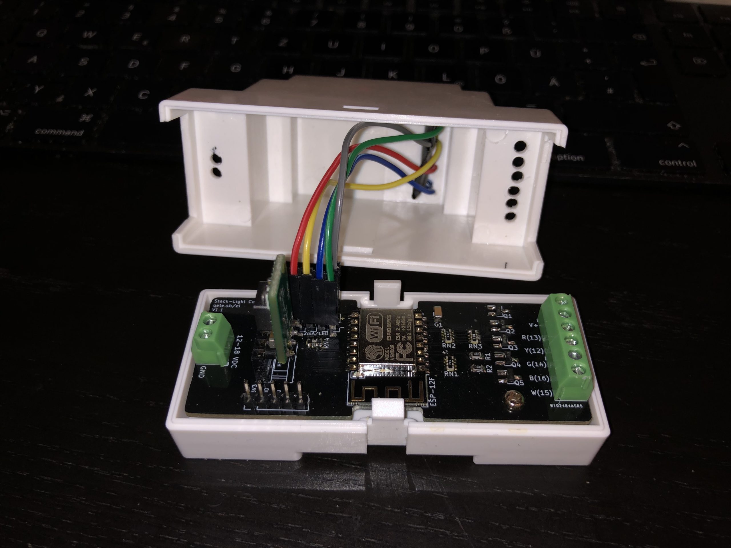
The case with the LEDs and the board installed 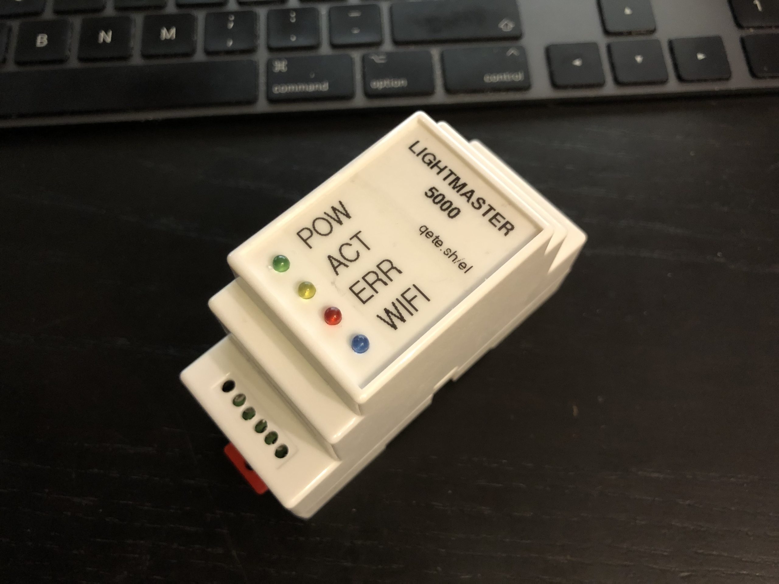
Completed 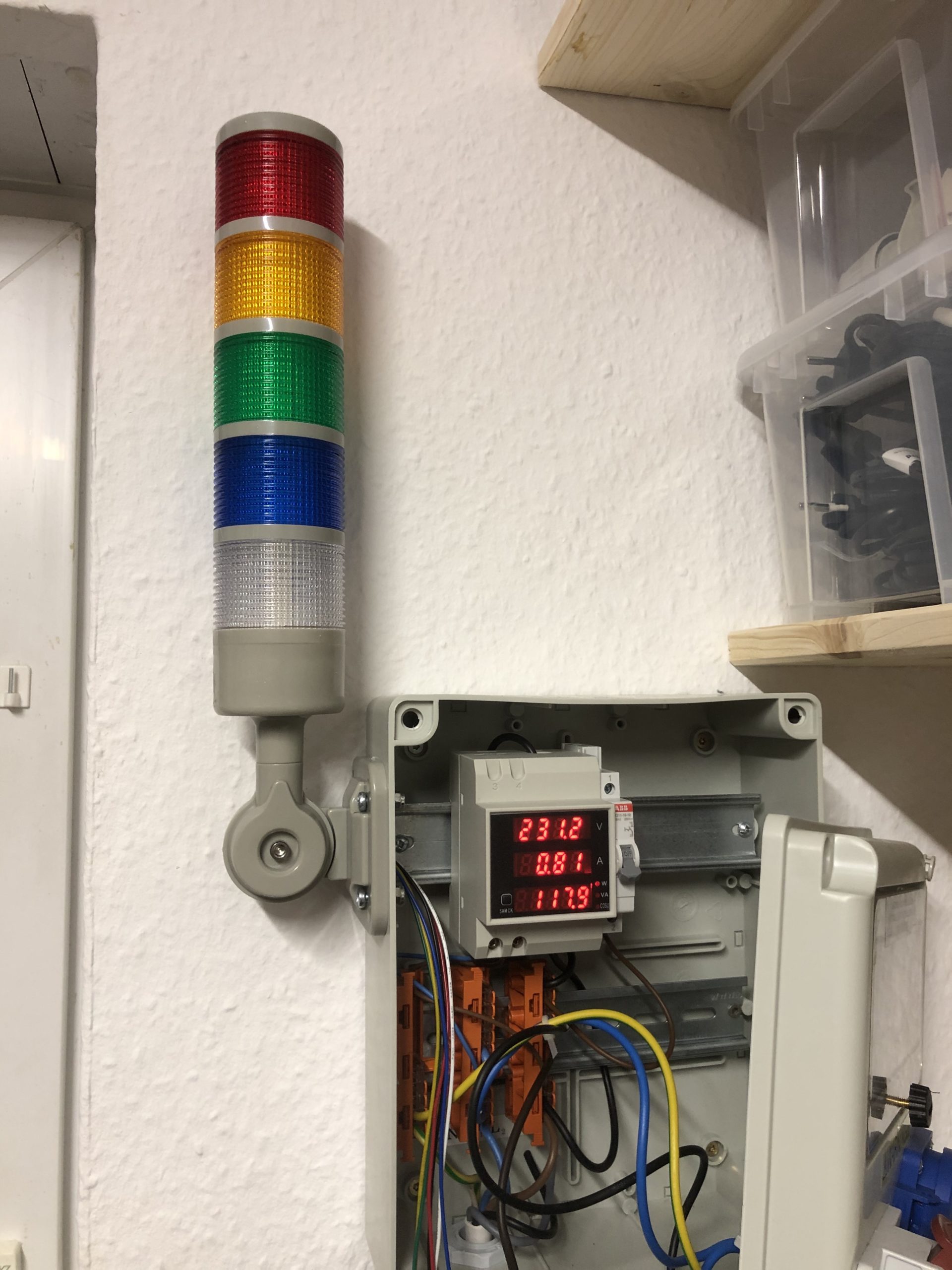
The light mounted to the fusebox 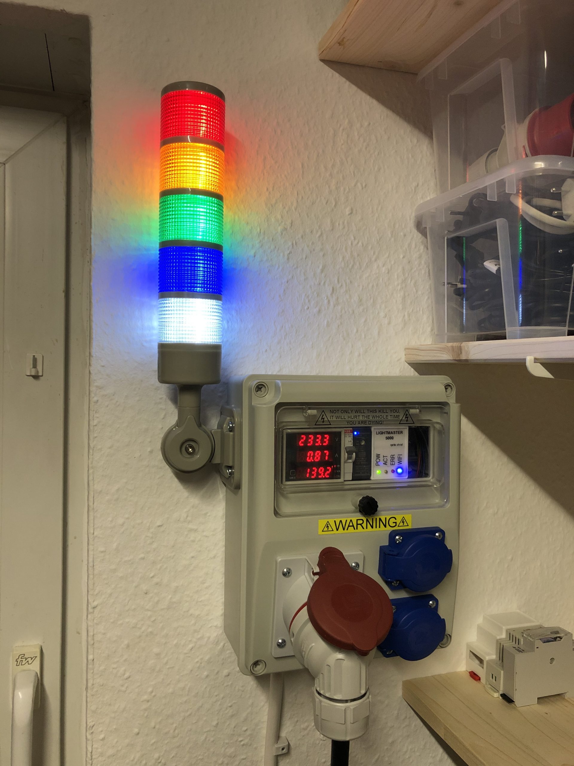
Everything installed and running! 
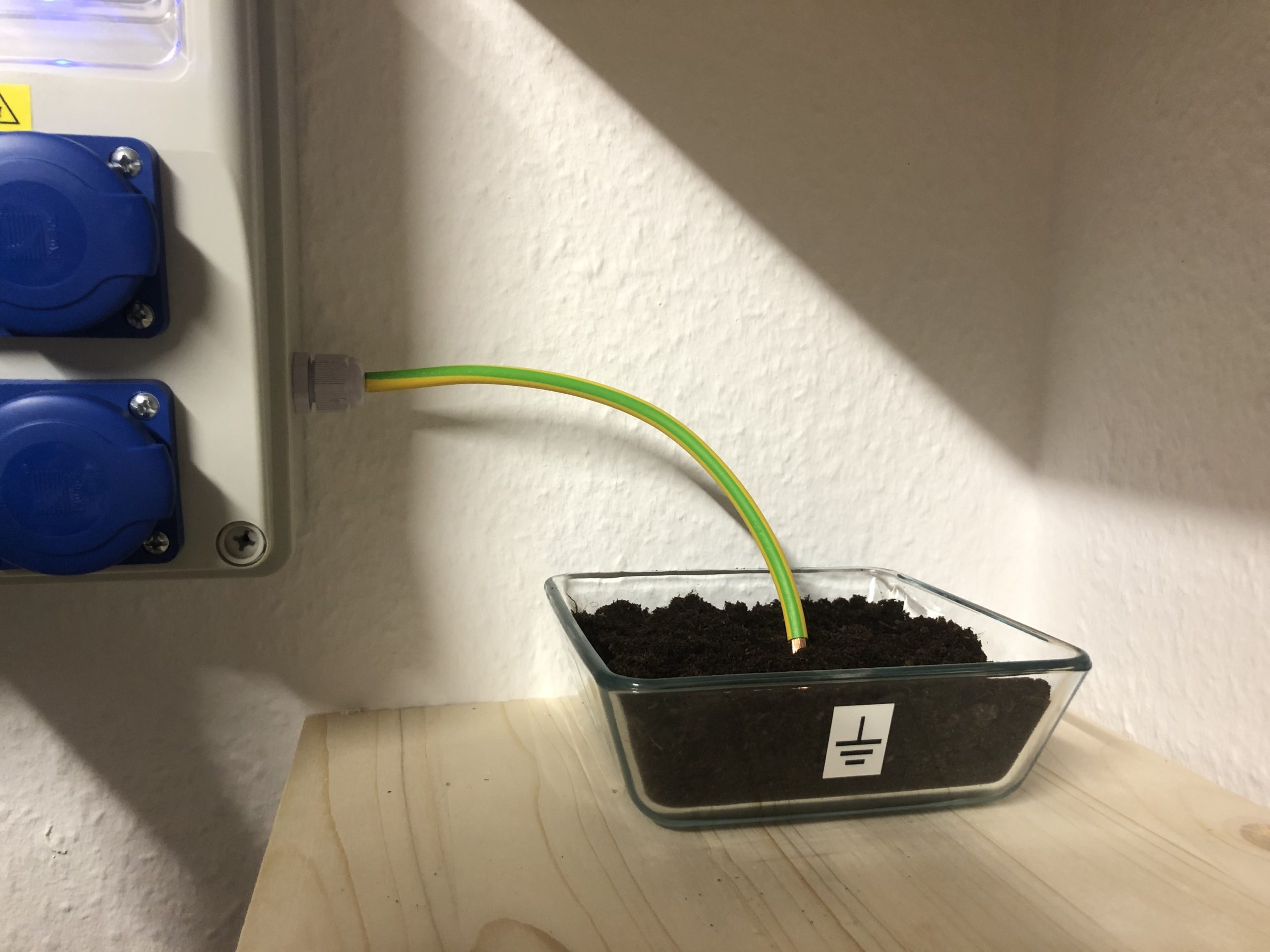
Proper earth connection!